The purpose of this lab was to create a game using two inputs and one Arduino output. The game itself was created using P5.js and serial communication. For my game, I utilized a potentiometer and a light sensor to control a one-person game of pong based on Coding Train’s example.
The game is an unwinnable game of Pong where the opponent is a static wall. There is also no means of scoring, either in time or points, rendering the game an exercise in futility.
The Circuit
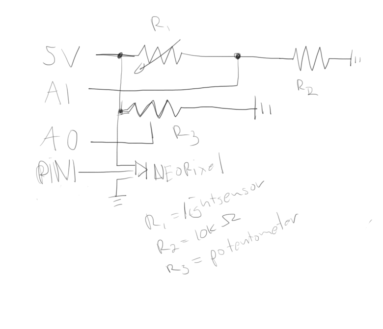
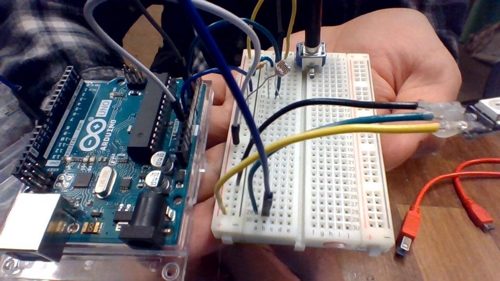
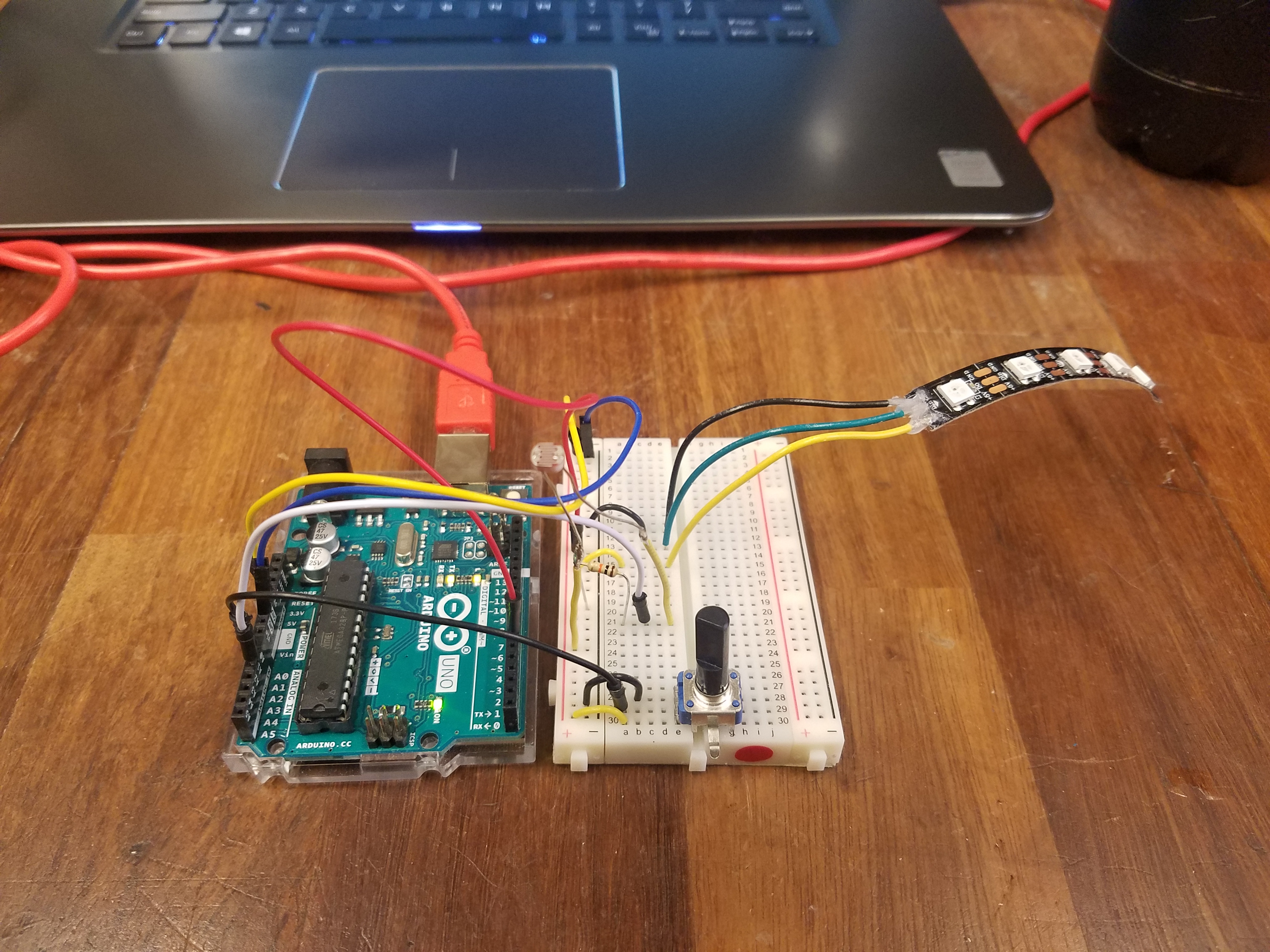
The Arduino circuit uses a potentiometer, a lights sensor with a 10k dropdown resistor, and a 5 LED strip of Neopixels. The potentiometer controls the paddle, the light controls the speed of the ball, and the LEDs display how many lives the payer has left
Circuit
The Arduino Code
The Arduino code first sets up the pins and the strip. Next, it sends the values from the analog pins to P5. Lastly, it checks for serial input and changes the Neopixel accordingly.
The P5 Code
The P5 code is based on Coding Train’s Pong example. I mostly used this as a basis for how to do collision detection and general code structure. I also added a game state to pause the game when the player eventually loses. Since the draw function is based on FPS, I was able to use that was a makeshift timer.
This lab dealt with analog inputs and variable resistors. Variable resistors are used in many sensors such as light sensors, flex sensors, and pressure sensors.
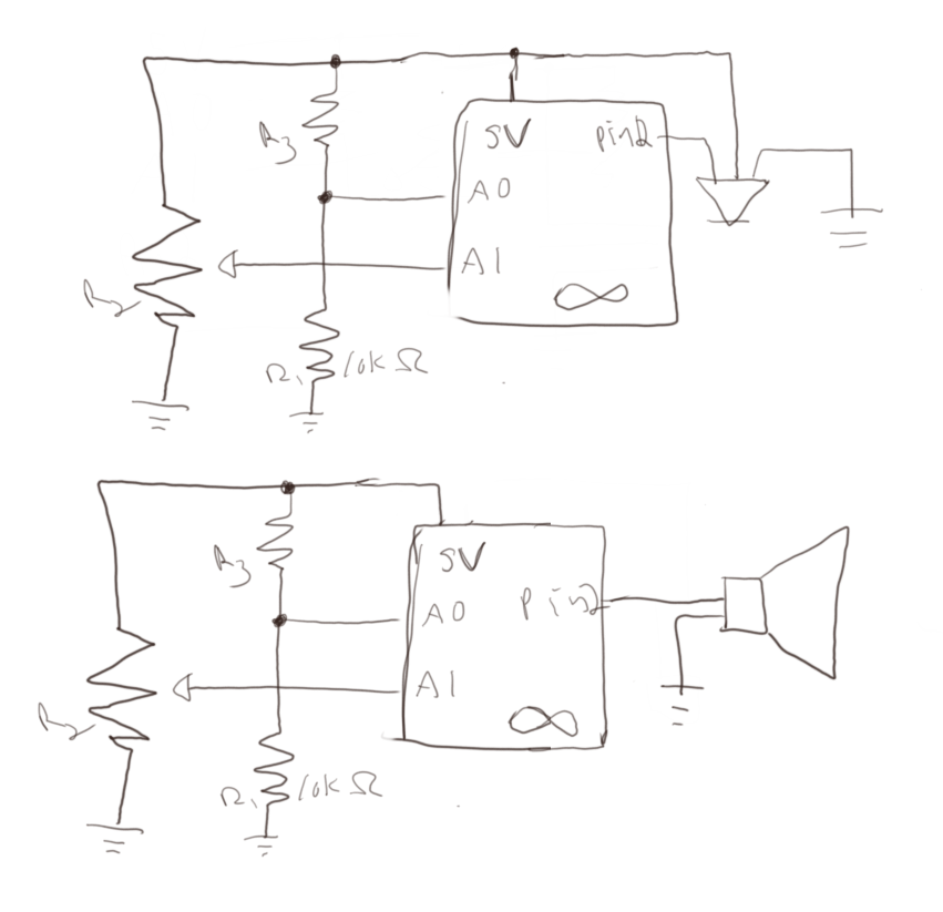
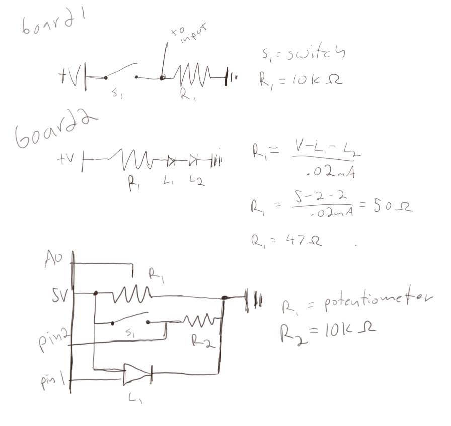
Schematics for both parts of the lab
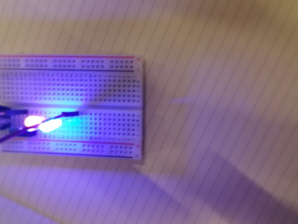
For the first part of this lab, I used a potentiometer and a light sensor to control a Neopixel LED strip. The amount of light input controlled the color of the strip and the potentiometer controlled the number of lit LEDs. The input was mapped to the outputs using the map() function
Circuit with two analog inputsPicture of the first circuitVideo of the first circuit in action
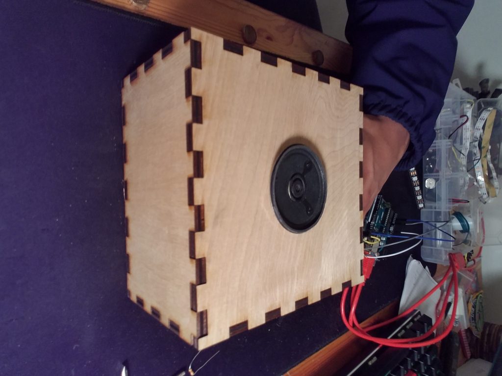
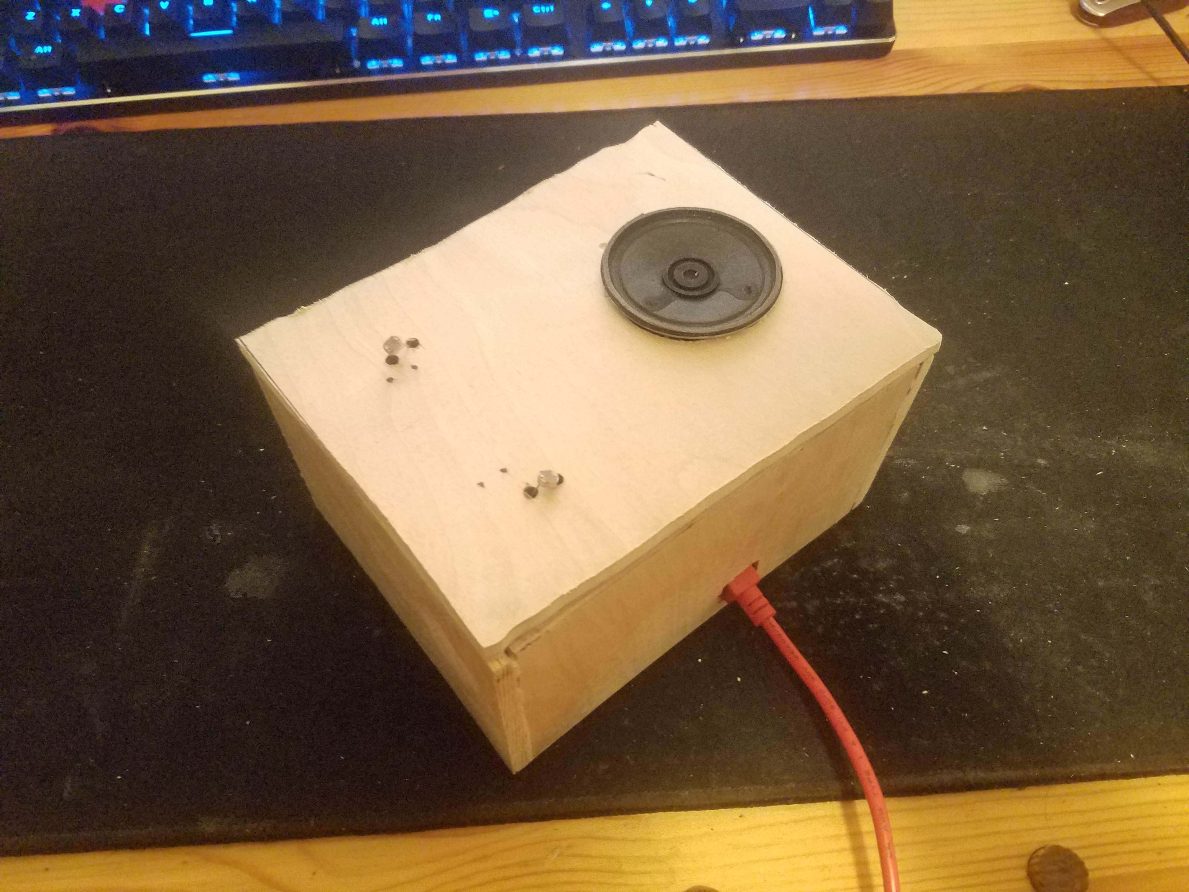
For the second part of this lab, I used the same inputs and instead used a speaker as output. This time the light sensor controlled the pitch mapped to between 31 and 1000. As sound changes logarithmically, this should be done using a different mapping function. The potentiometer controlled the duration of the sound blips.
Video of the speaker with two analog inputs
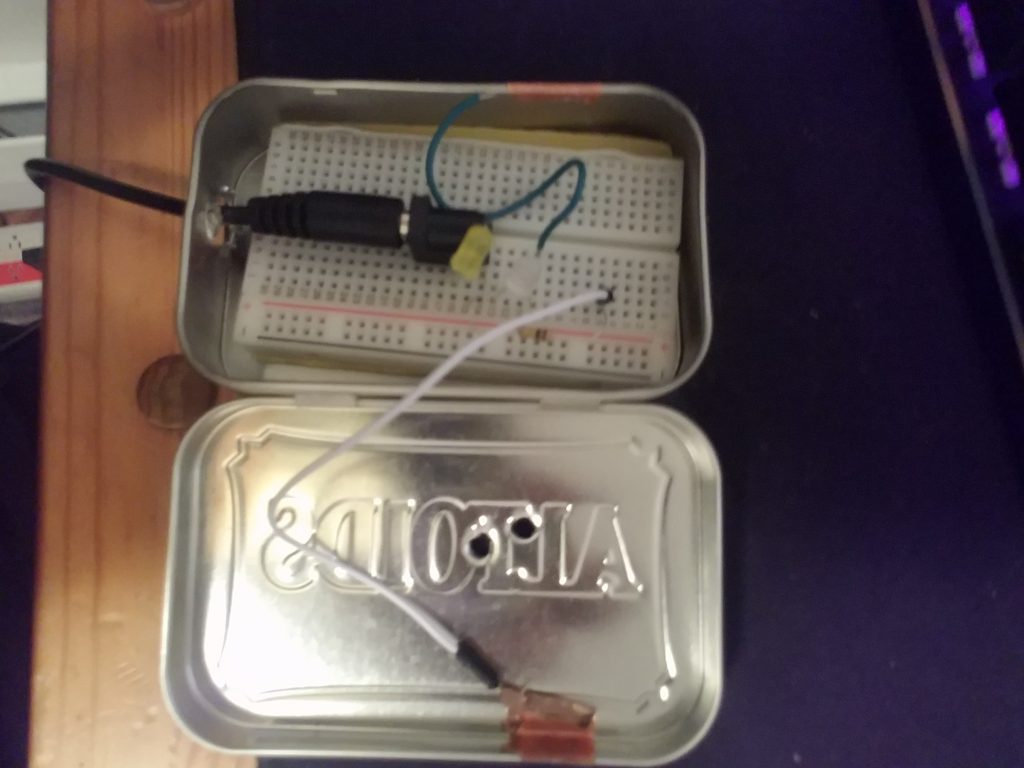
The last part of this lab was to create a box that had two outputs and multiple inputs. This is not that box.
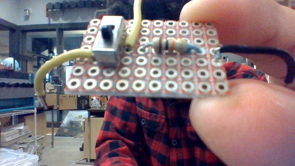
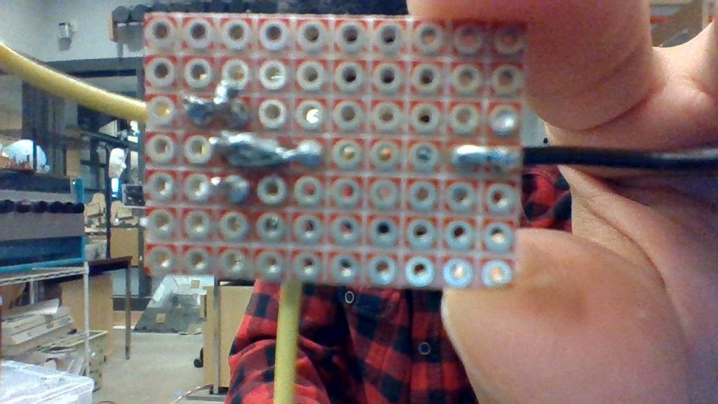
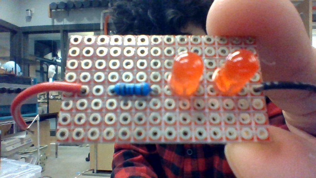
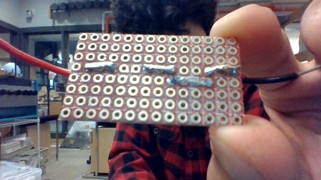
The first part of this lab was to create two separate breakout borders. The first one is a switch with a drop-down resister. The second one is two LEDs in series. I wasn’t able to get a 47-ohm resistor for the second board so I used a 100-ohm instead.
All schematicsSwitch with dropdown resistorSoldering on breakout boardTwo LEDs in series with 100-ohm resistorSoldering on two LED board
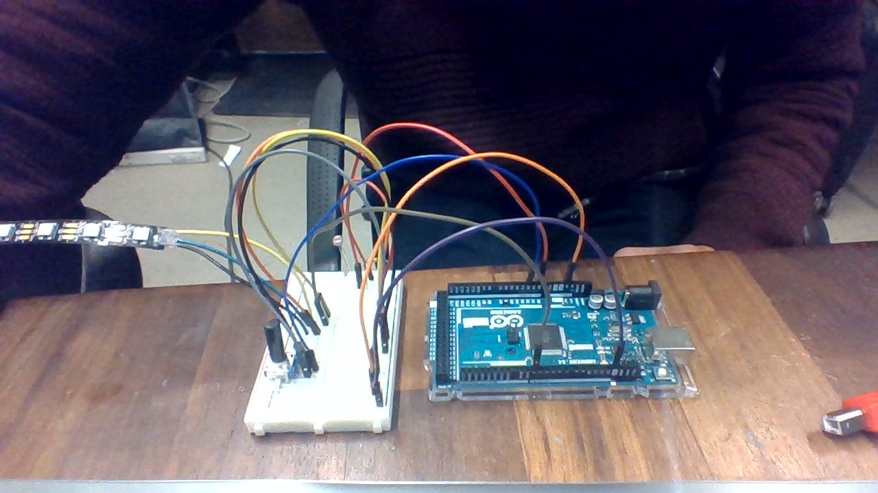
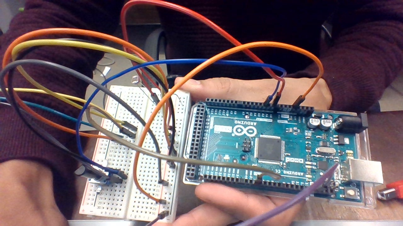
The second part of the lab was to create a circuit that controlled a NeoPixel strip with two inputs. for my two inputs, I used a potentiometer and a switch. The potentiometer controlled the colors and the switch turned it on and off. The color transition was taken from Adafruit’s strand test.
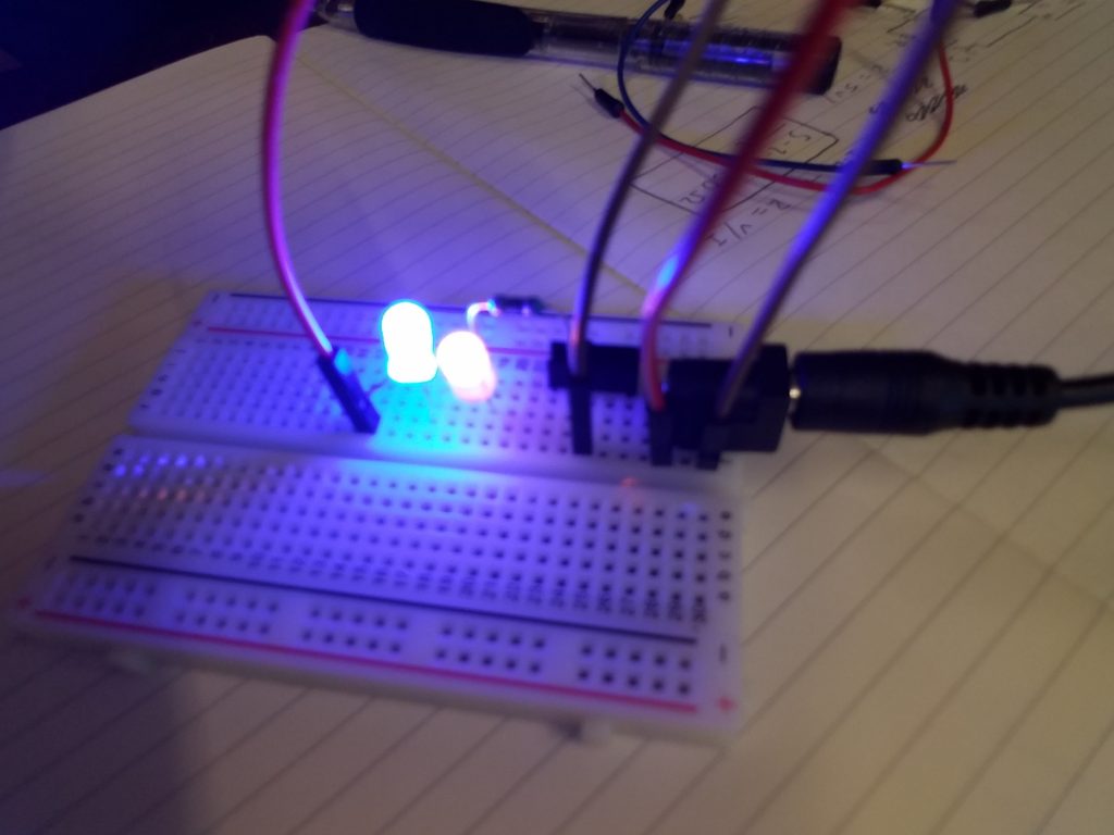
In this lab, we created two circuits: LEDs in series and LEDs in parallel.
The LEDs in series used a 3.4V, 30mA blue LED and a 2V, 20mA yellow LED. As the total voltage was more than the 5V a 7805 voltage regulator will give out, it was not included.
The LEDs in parallel used the same LEDs as well as a voltage regulator.
For the last part, I made the switch and enclosure together. Unfortunately, I blow out my LEDs as well as broke my camera and was not able to have a video of it in action
For the mask, I have obtained all of the sensors, most of the actuators, and all of the outer mask materials. Fortunately, all of the actuators use a simple analogRead to get input and all of the actuators I have worked with before.
As you can see the Myoware sensor output an analog signal that was easily mapped to the Neopixel.
Myoware Sensor in actionPulse Sensor in actionPulse monitor and servo in action
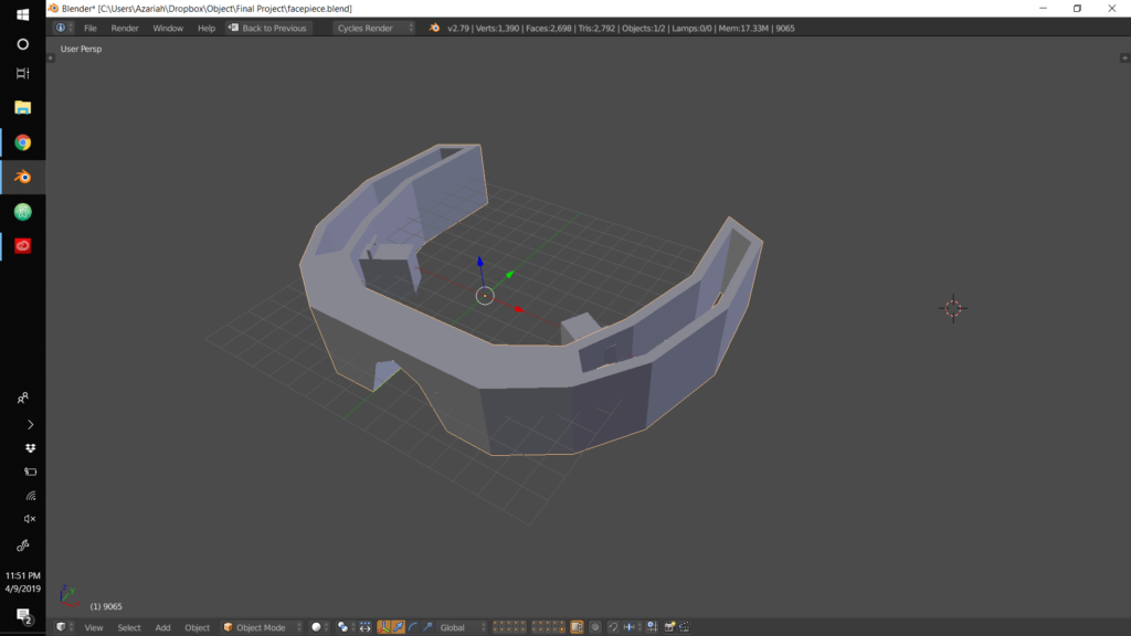
For the mask materials, I purchased some snowboard boots and have reformed those into the front part of the mask.
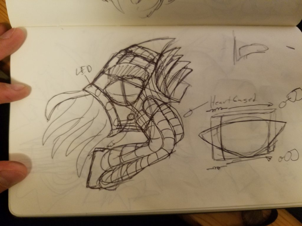
I also created an interior of the mask that will house the servos and actuating third eyelids. I opted for the third eyelids as they are more reptilian than eyebrows or eyelids. I created several iterations of these using cardboard but, due to most laser cutters not allowing particle board, I was unable to create a final cut of these.
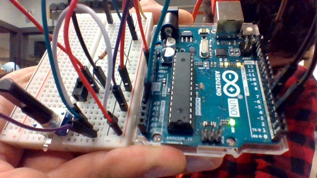
The point of this lab was to create a connection between an Arduino and p5.js. p5.js is a JavaScript library based on Processing, a language built for easy sketch-coding. For this lab, we required a sensor, an actuator, an Arduino, and a computer. A lot of the lab’s challenge was in the computer installation and setup of the p5.js code.
Arduino to p5
After starting a new sketch in the p5.js web editor, we added p5.serialport.js which allowed us to access the ports from the browser.
On the arduino side, we created two sensors that then sent the data back to the computer via serial communications. I used a potentiometer and a light sensor. The values from these were sent back in ASCII as comma separated values.
The p5.js then parsed this and mapped them to a circle’s height and width.
Here the potentiometer is controlling the width of the circle. The potentiometer readings were rather jittery and with the frequency of the readings, the circle appears to jump sizes.
Arduino potentiometer controlling circle width
P5 to Arduino
For this part of the lab, neither the Arduino or the codes changed much. There was the change that the Arudino was reading instead of printing and had to do its own try/except error catching.
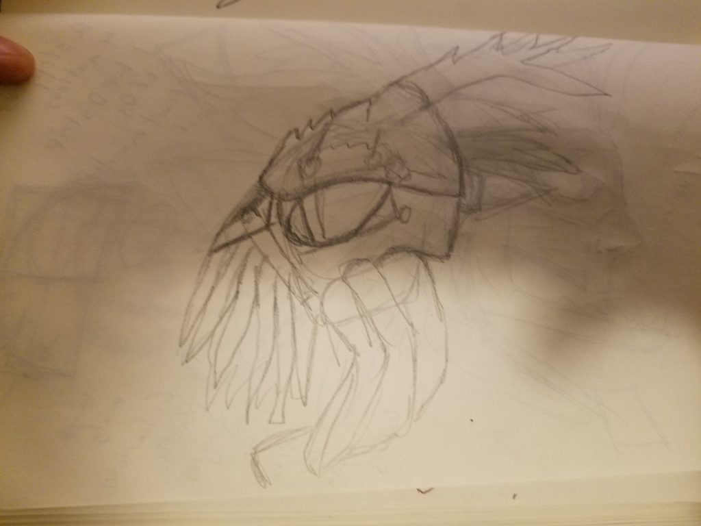
My interactive object will be a Cthulhu mask made from recycled materials. The mask will contain three separate interactive systems. The first will be moving eyebrows, the second will be voice activated lights on the mouth tentacles to accentuate speech, and the last one will be a heart monitor which propagates lights through the mask in a breathing manner.
The mask will build off my previous experience making this mask. I liked making the mask as an art project. I would love to refine my technique and build onto the existing skill set.
In this lab, 3 types of motor systems were used: DC, Servos, and Steppers. Two systems were all very similar in that they used an H-bridge to control the motor. The servo motor was simpler as it only used the built-in Arduino library
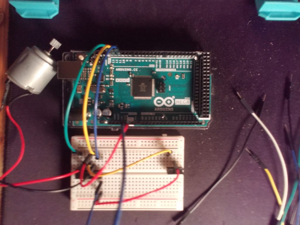
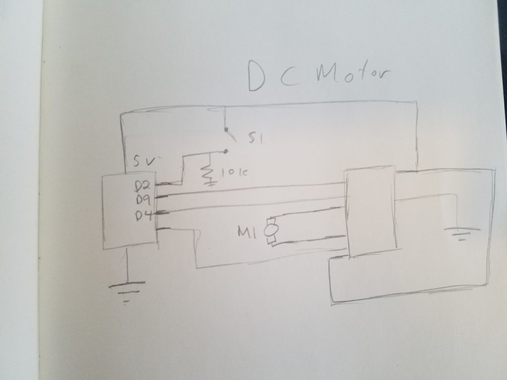
DC Motor
DC motors have a single speed and can only change direction when the polarity is reversed. In order to change the direction of the motor the H-bridge’s pins were manually coded.
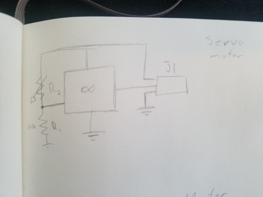
Servo Motor
Servo motors can only rotate 180 degrees but have increased torque. In order to change the rotation, the output was mapped to a pressure sensor.
The coding for this is very simple as the Servo will accept a single value to change the rotation.
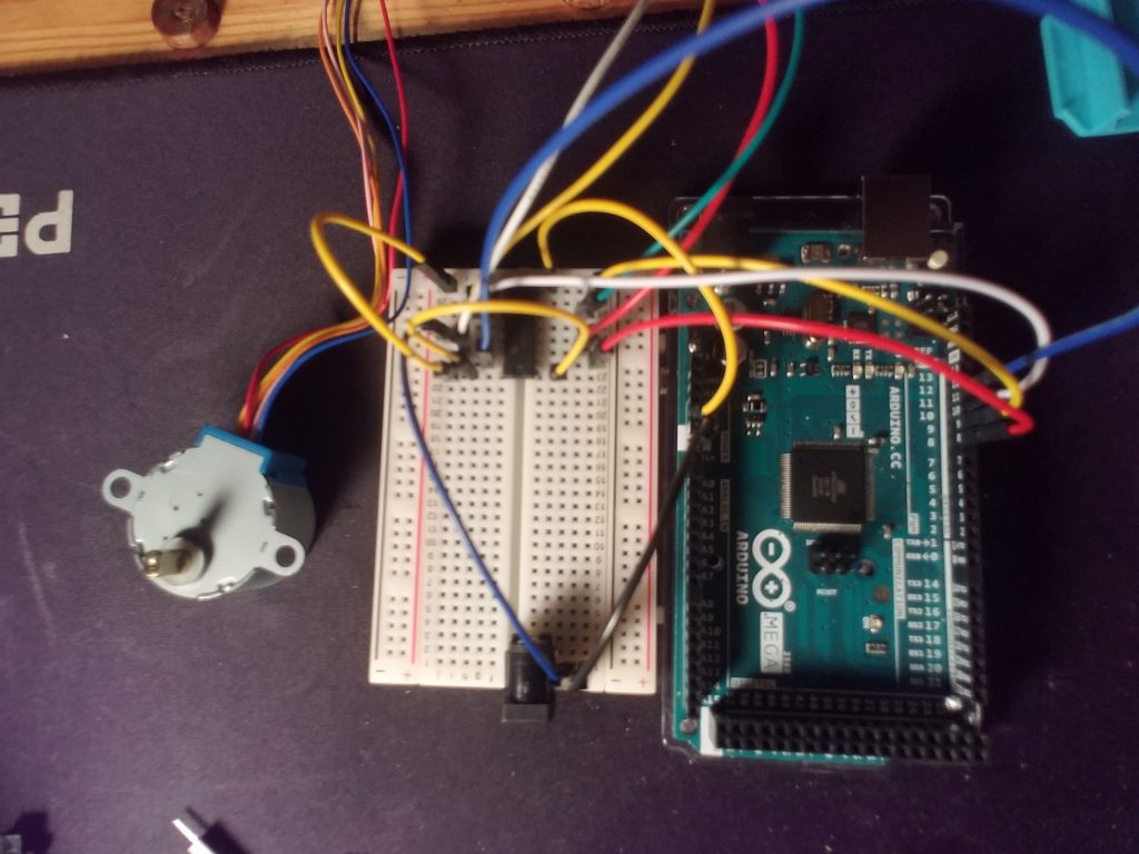
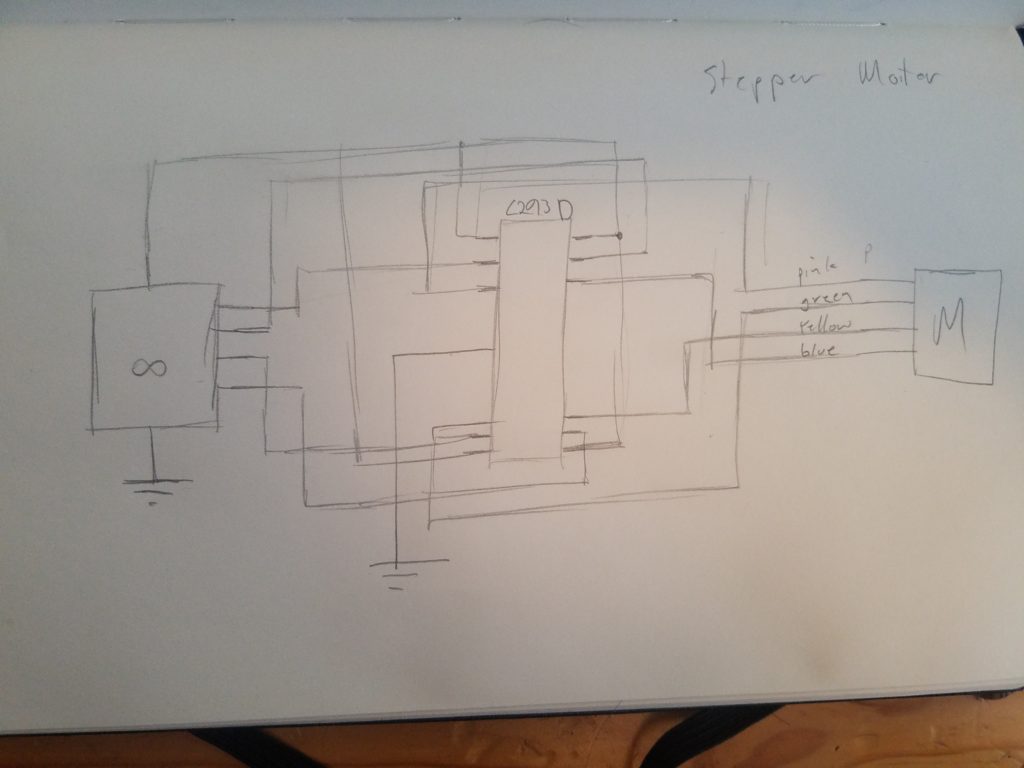
Stepper Motor
Stepper motors, while more complex then DC or Servo motors, they have the capability of increased torque and a full cyclic range or motion. The schematic for this was a lot more complex as every pin on the H-bridge was used
Because of Arduino’s built-in libraries and example codes, coding the stepper was very easy. I did have trouble getting it to work as the number of steps in a revolution has to be changed based on the stepper. Additionally, the RPM had to be lowered to the point that the motor will not burn out.
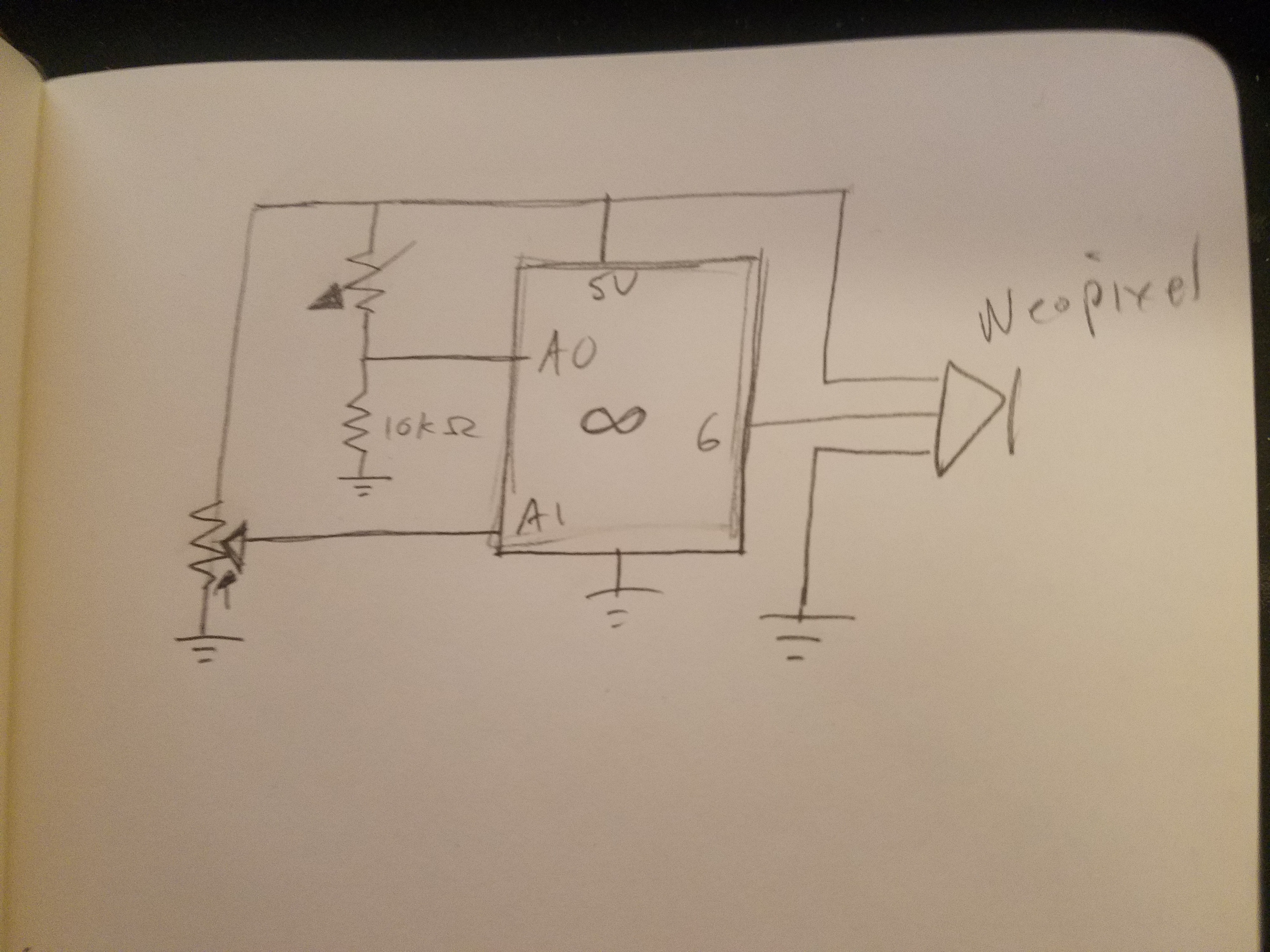
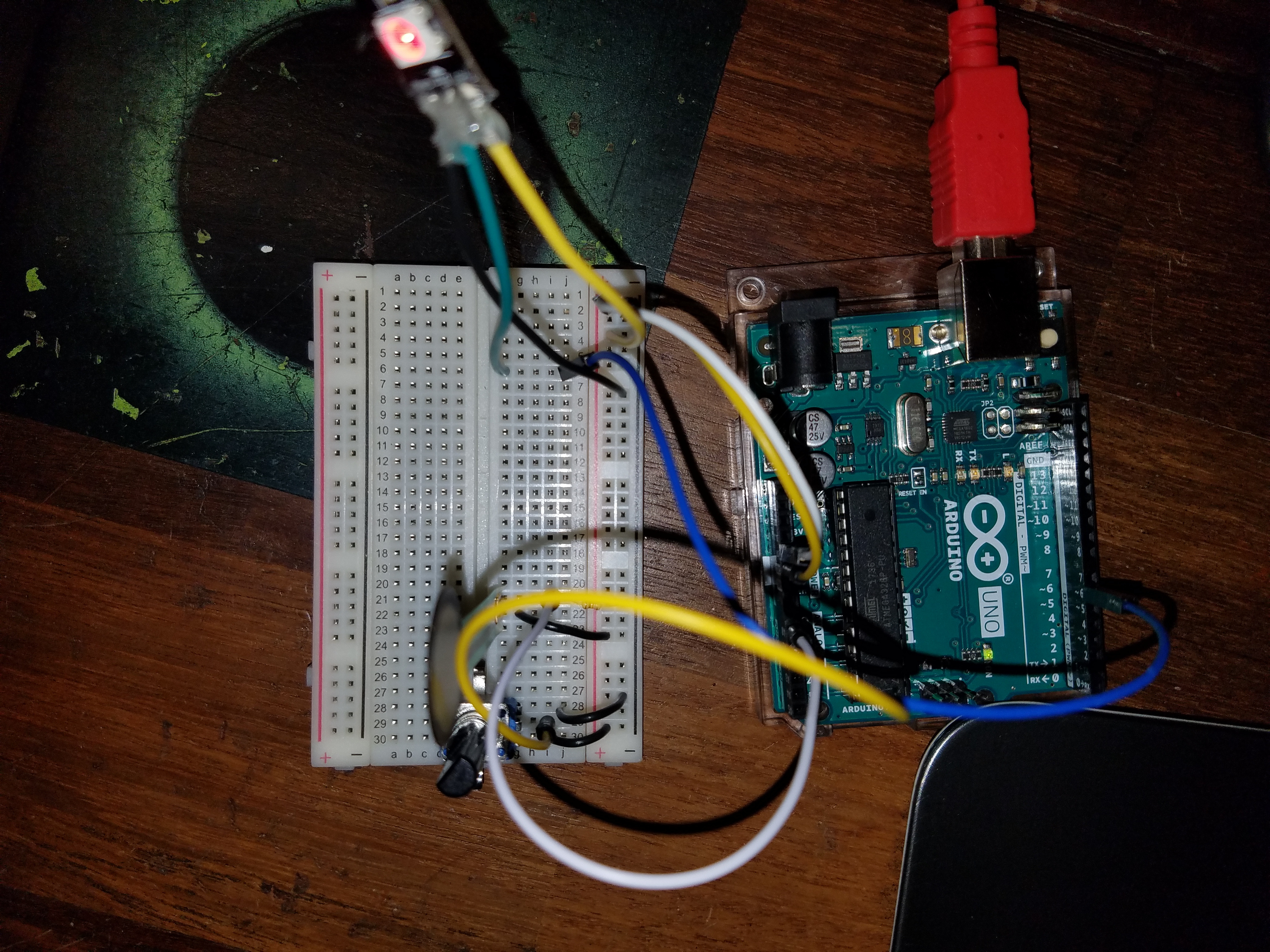
The first part of this lab was to create a simple analog input with varying output. For mine, I used a pressure sensor, a potentiometer, and NeoPixels to create a rudimentary strong man device. The number of lights corresponded to the pressure and the color was changed by rotating the potentiometer.
Schematics of part 1
I adopted the WheelPosition function from the AdaFruit strandtest.ino in order to convert the scalar potentiometer readings to cyclic color values. The one issue with this code is that as it updates every half second some pixels were given colors and then not reassigned to blank after the pressure was removed causing the colors to appear off at times.
Part 1 finishedPotentiometer readings in serial monitorVideo demonstration
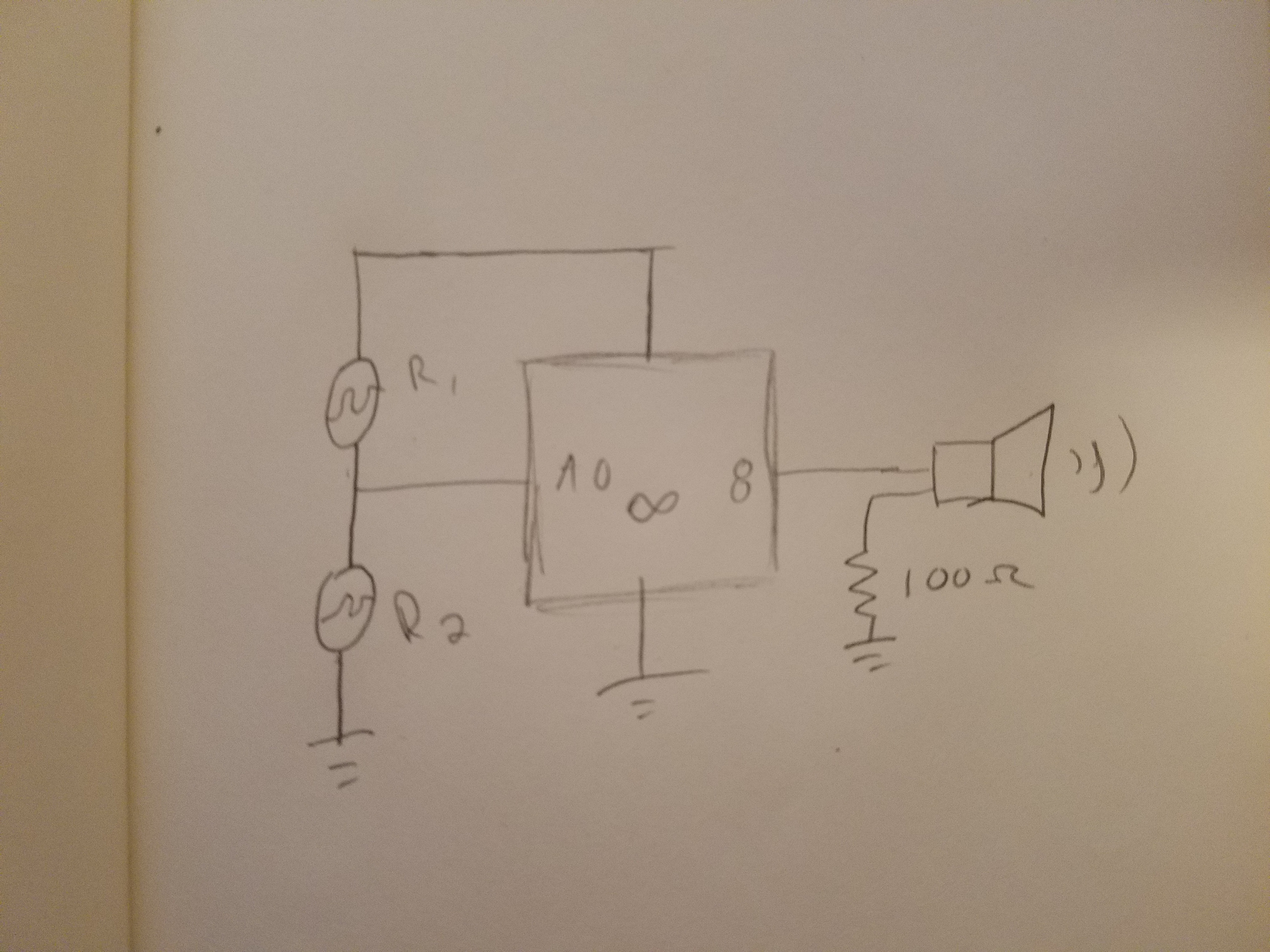
Part 2
In the second part, we used an analog input to control the tone of a speaker. I found the random buzzing that was created to be annoying so I changed it to notes.
Schematics for part 2
The note values were taken from Wikipedia.
Part 2 testing
For this project, I made a box from plywood. Unfortunately, I was unable to locate my jigsaw and had to use a circular saw (which was too large for such a small project) and a dremel (which was too small). I made most of the pieces larger than needed and then sanded down to size.