Object Round 2: Entry 6

Final Project

Description

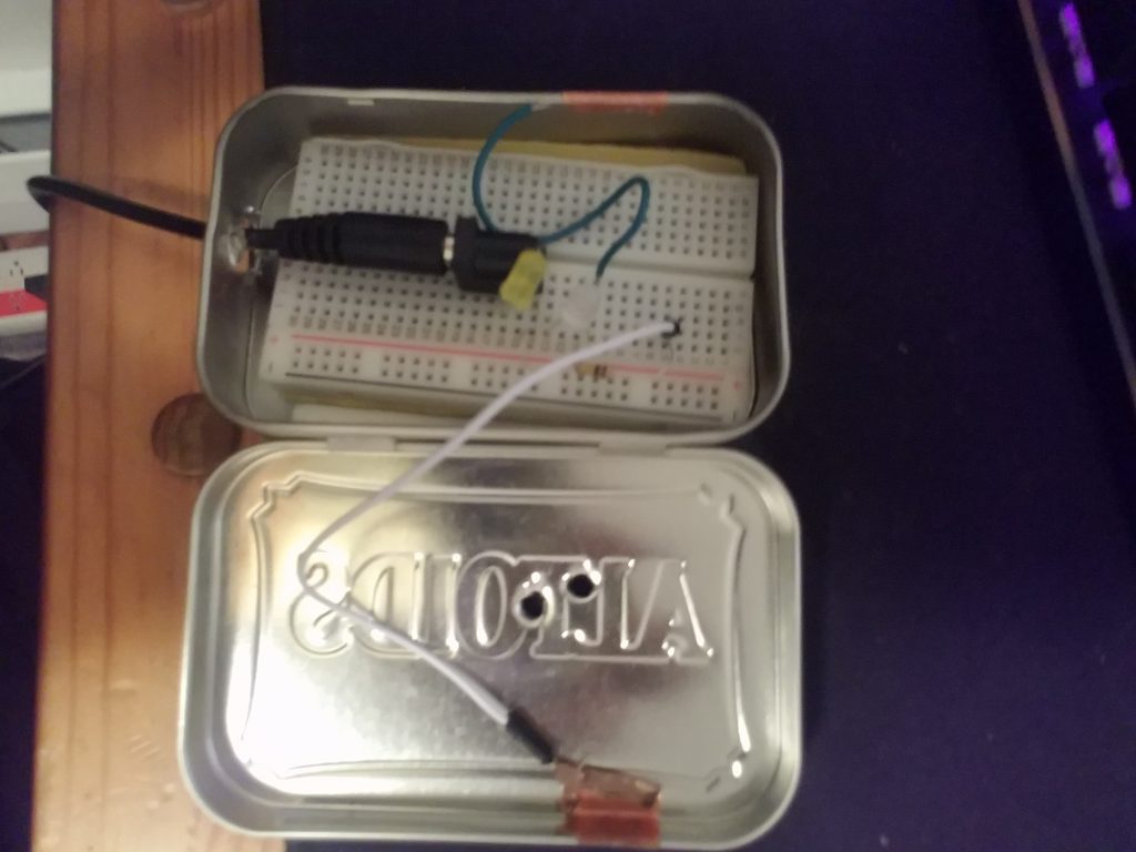
The Turkish Typewriter is an interactive object that will take words spoken near it and convert them into poems. I was inspired to create this creation because it is a nice combination of technological fabrication, coding, and art. While it wasn’t my first idea, I had planned on creating something far more controversial and purely code-based, the idea for a physical installation stuck with me. I wanted this project to at least give people pause, to stop and consider what the project meant and what art is as a whole.

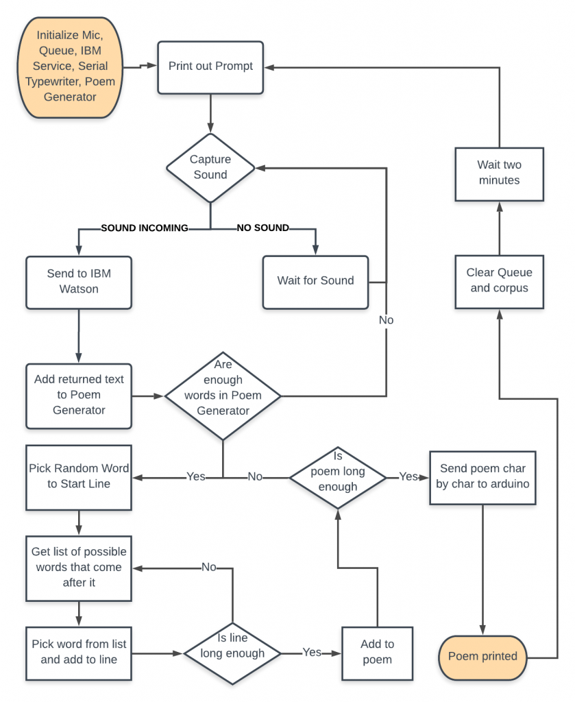
The project works by capturing sound and sending it to IBM’s Watson to convert it to text. The resulting text is then returned and entered into a poem generator. The poem generator creates poems using Markov chains. Markov chained text takes a couple of words from a corpus and then finds what words go after that string in a given corpus. Then the last two or three words of the resulting string are used to repeat the process until the desired length is reached.

The poem generator works backward from the end of a line and creates Markov chains of two words until 5 or 7 syllables are reached. The lines are built backward in order to accommodate rhyming functionality.

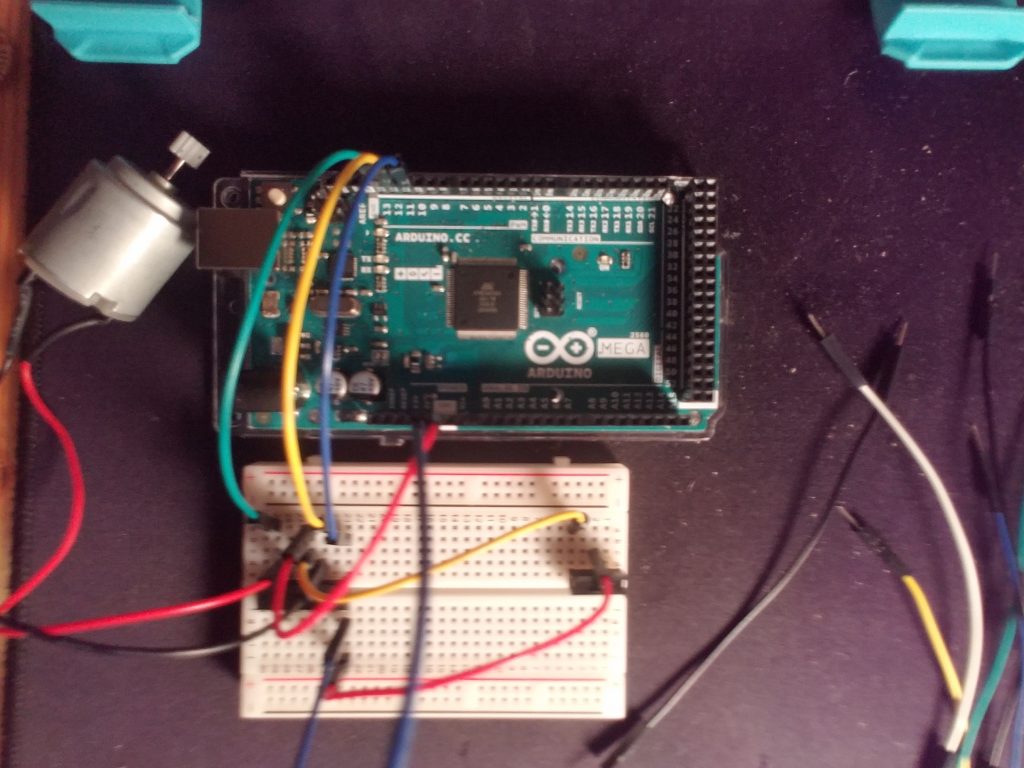
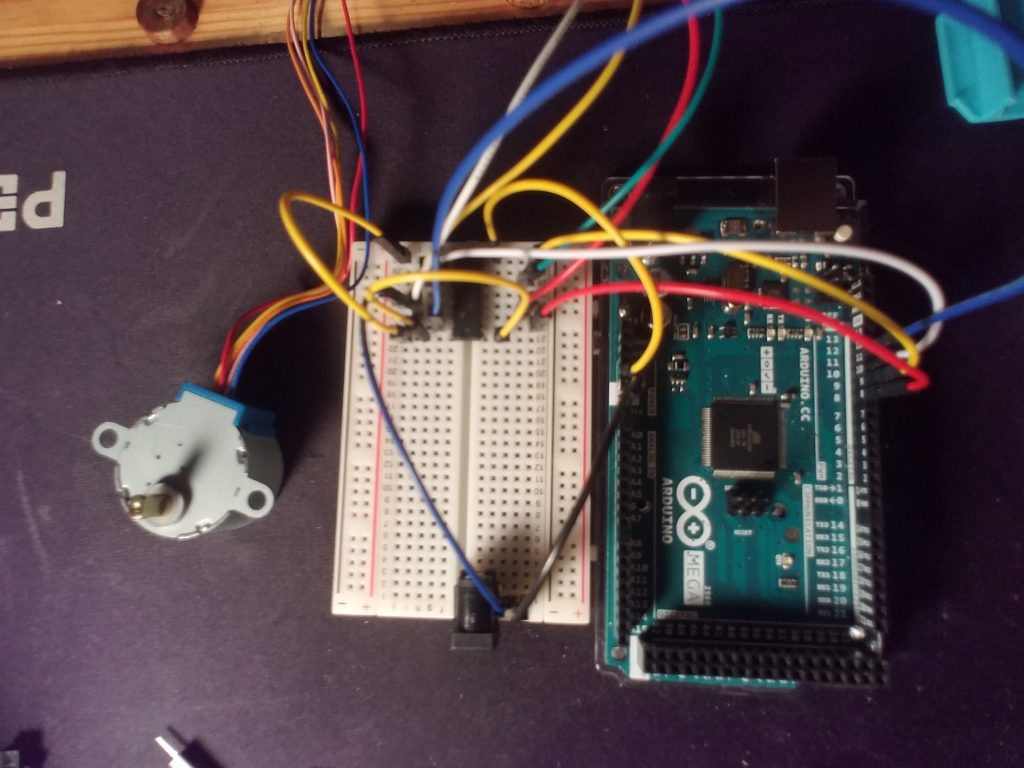
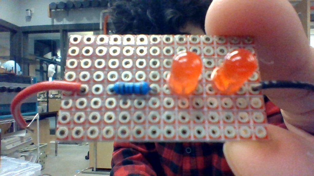
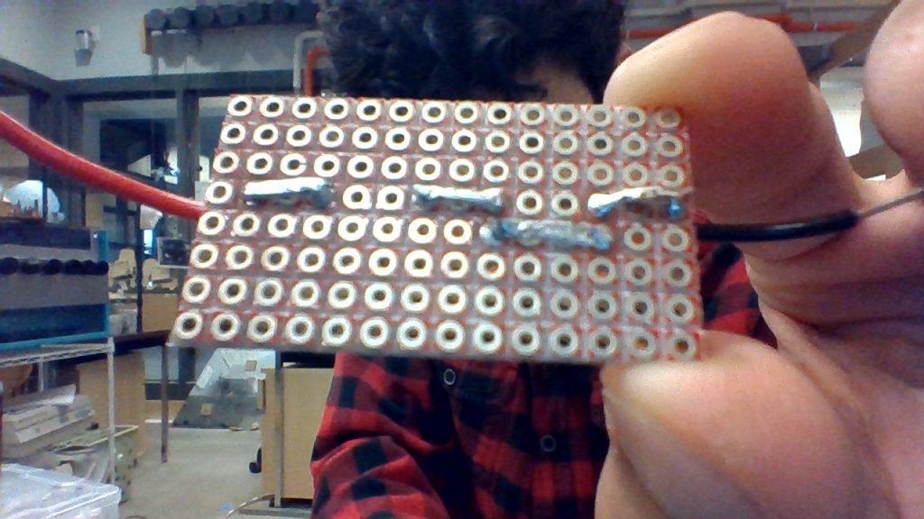
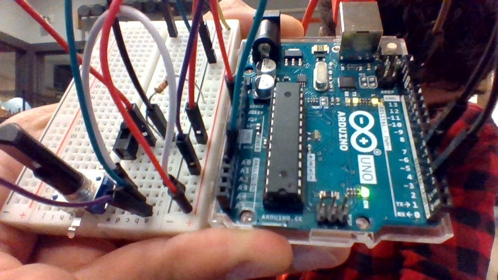
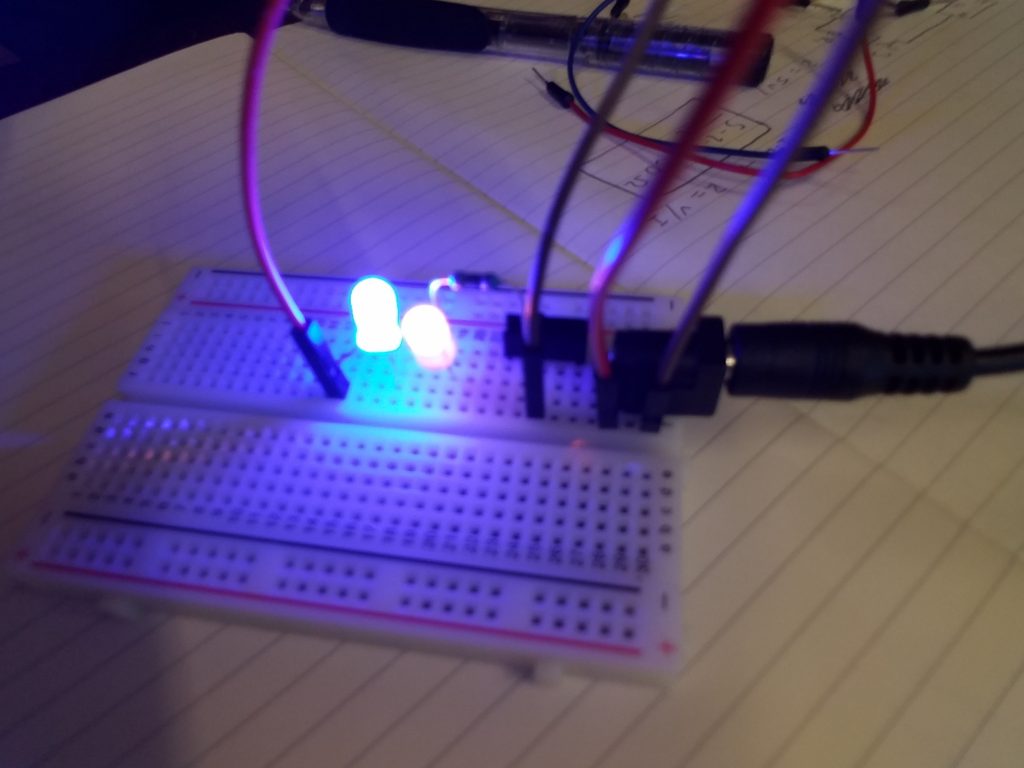
After the length is reached, the poem is sent character by character to an Arduino which triggers the two relevant pins in a matrix. For example, when an ‘n’ is sent, the Arduino triggers transistor 1 and 11. These transistors then close a circuit, trigger the typewriter’s carriage to print an ‘n’. In addition, the triggered transistors close the circuit for an led. The LEDs should ideally give additional feedback to the users and the appearance that the system is working

There was a single issue with there not being the keys not firing when on the same board as the lights. This issue may have been the typewriter pins being grounded by the lights or there not being enough power to power both the lights and the transistors.

Interactions

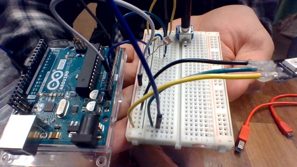
Users are able to interact with the machine by reading the given prompt and responding to it in a verbose manner. The more verbose and diverse the resulting corpus is, the better the resulting poem will be.
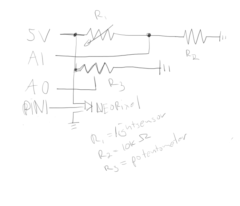
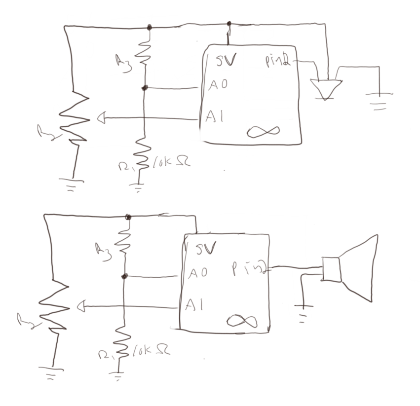
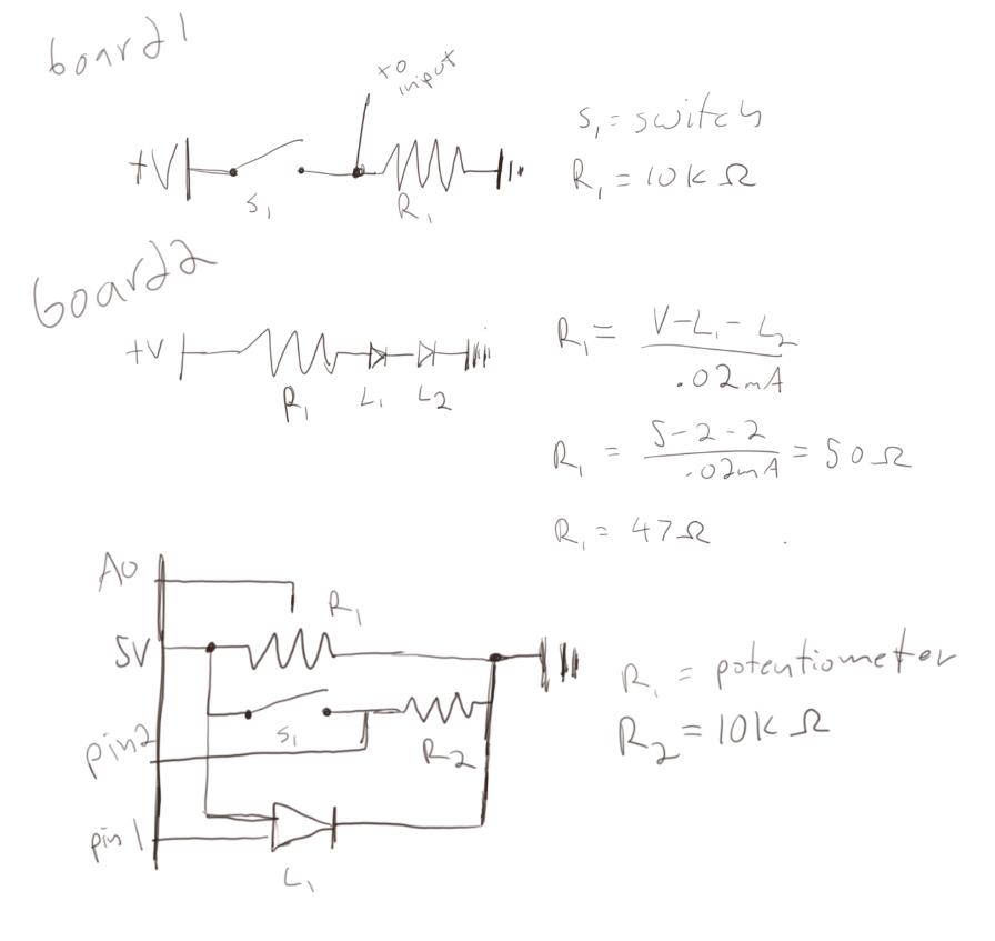
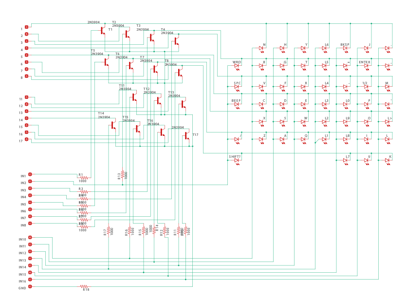
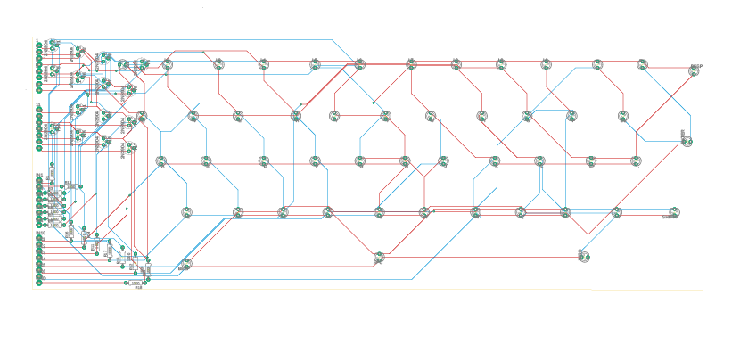
Schematics

The schematics for this project were created in Eagle and printed by JLCPCB. There is an issue on the board that the ‘T’ and ‘Y’ keys are switched.

Video

Video of Interaction
Video of Lights

Code

Half of the code for this project was written in Python. The Arduino half was written in Arduino. All code (including prototypes and further iterations can be found here

Object Round 2: Entry 5

Lab 5: Motor Lab

For this lab, we made circuits to control a DC motor and a stepper motor using an H-bridge

The DC Motor

The DC motor was controlled using the H-bridge to switch the polarity of the motor and switch the direction.

The Stepper Motor

The stepper motor was a small 28byj-48. The number of steps per revolution varied from what the datasheet said.

Object Round 2: Entry 4

Lab 4: Serial

The purpose of this lab was to create a game using two inputs and one Arduino output. The game itself was created using P5.js and serial communication. For my game, I utilized a potentiometer and a light sensor to control a one-person game of pong based on Coding Train’s example.

The game is an unwinnable game of Pong where the opponent is a static wall. There is also no means of scoring, either in time or points, rendering the game an exercise in futility.

The Circuit

The Arduino circuit uses a potentiometer, a lights sensor with a 10k dropdown resistor, and a 5 LED strip of Neopixels. The potentiometer controls the paddle, the light controls the speed of the ball, and the LEDs display how many lives the payer has left

Circuit

The Arduino Code

The Arduino code first sets up the pins and the strip. Next, it sends the values from the analog pins to P5. Lastly, it checks for serial input and changes the Neopixel accordingly.

The P5 Code

The P5 code is based on Coding Train’s Pong example. I mostly used this as a basis for how to do collision detection and general code structure. I also added a game state to pause the game when the player eventually loses. Since the draw function is based on FPS, I was able to use that was a makeshift timer.

P5.js code

The Game

You just lost The Game.

Video of the game in action

Object Round 2: Entry 3

Lab 3

This lab dealt with analog inputs and variable resistors. Variable resistors are used in many sensors such as light sensors, flex sensors, and pressure sensors.

Schematics for both parts of the lab

For the first part of this lab, I used a potentiometer and a light sensor to control a Neopixel LED strip. The amount of light input controlled the color of the strip and the potentiometer controlled the number of lit LEDs. The input was mapped to the outputs using the map() function

Circuit with two analog inputs
Picture of the first circuit
Video of the first circuit in action

For the second part of this lab, I used the same inputs and instead used a speaker as output. This time the light sensor controlled the pitch mapped to between 31 and 1000. As sound changes logarithmically, this should be done using a different mapping function. The potentiometer controlled the duration of the sound blips.

Video of the speaker with two analog inputs

The last part of this lab was to create a box that had two outputs and multiple inputs. This is not that box.

A Box

Object Round 2: Entry 2

Lab 2

The first part of this lab was to create two separate breakout borders. The first one is a switch with a drop-down resister. The second one is two LEDs in series. I wasn’t able to get a 47-ohm resistor for the second board so I used a 100-ohm instead.

All schematics
Switch with dropdown resistor
Soldering on breakout board
Two LEDs in series with 100-ohm resistor
Soldering on two LED board

The second part of the lab was to create a circuit that controlled a NeoPixel strip with two inputs. for my two inputs, I used a potentiometer and a switch. The potentiometer controlled the colors and the switch turned it on and off. The color transition was taken from Adafruit’s strand test.

Object Round 2: Entry 1

Lab 1

In this lab, we created two circuits: LEDs in series and LEDs in parallel.

The LEDs in series used a 3.4V, 30mA blue LED and a 2V, 20mA yellow LED. As the total voltage was more than the 5V a 7805 voltage regulator will give out, it was not included.

The LEDs in parallel used the same LEDs as well as a voltage regulator.

For the last part, I made the switch and enclosure together. Unfortunately, I blow out my LEDs as well as broke my camera and was not able to have a video of it in action