Lab 2: Digital I/O
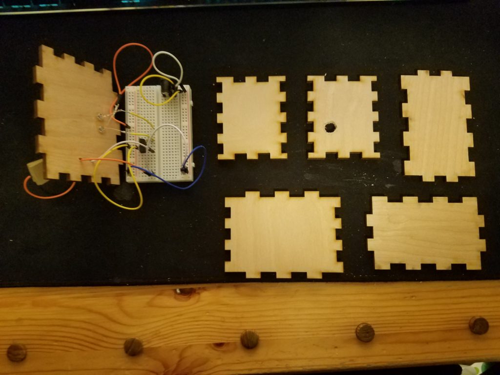
Part 1: Soldered Breakout Board
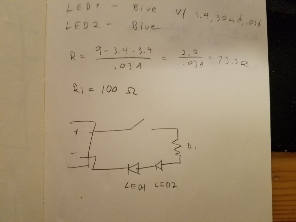
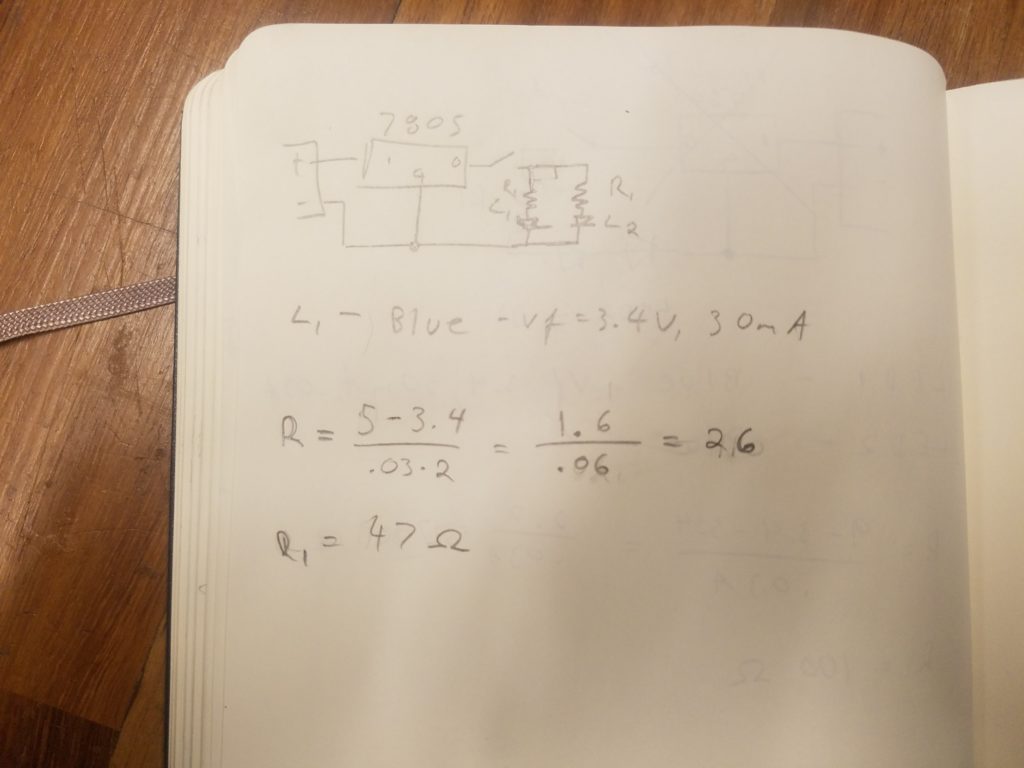
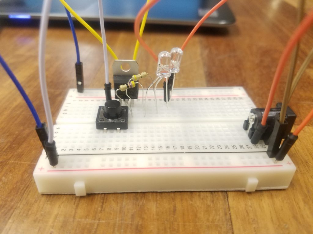
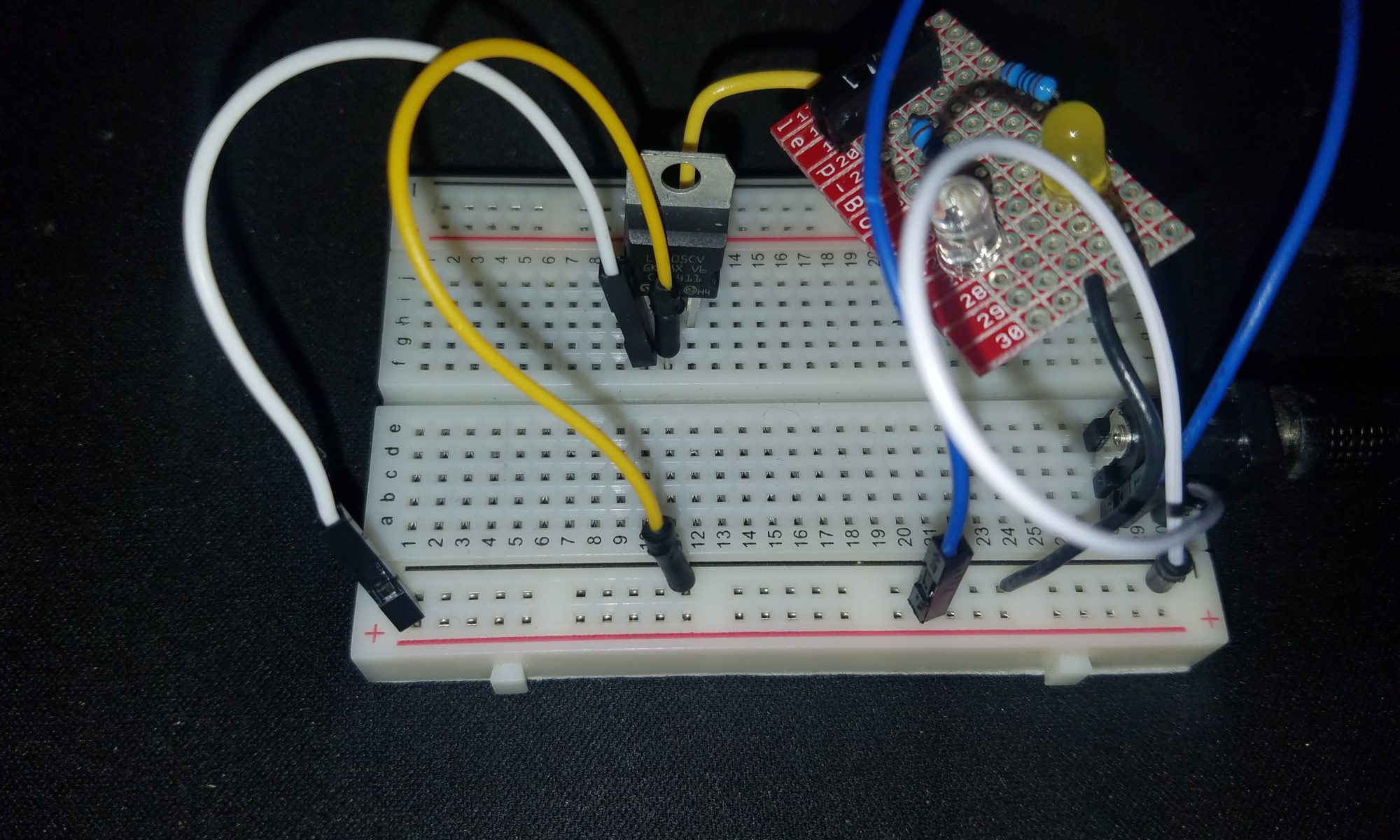
For this excercise, we created single parts of a circuits. For mine, I made 2 LEDs in parallel. This was harder as there were several wires that needed to be soldered together.
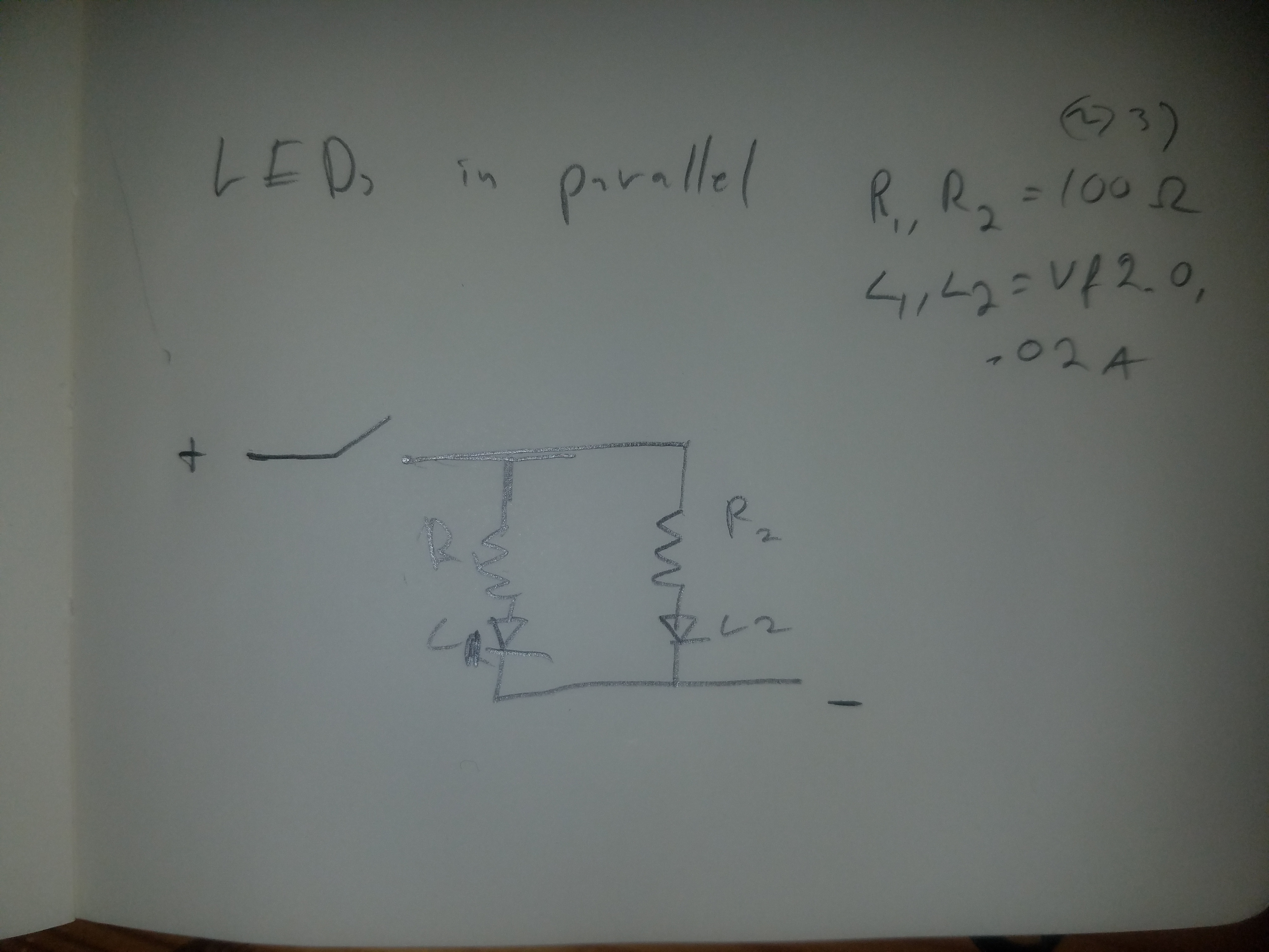
After calculating the resistance I set up the switch, resistors, and LEDs. Luckily both green and yellow LEDs have the same forward voltage so there was no need for extra calculations.
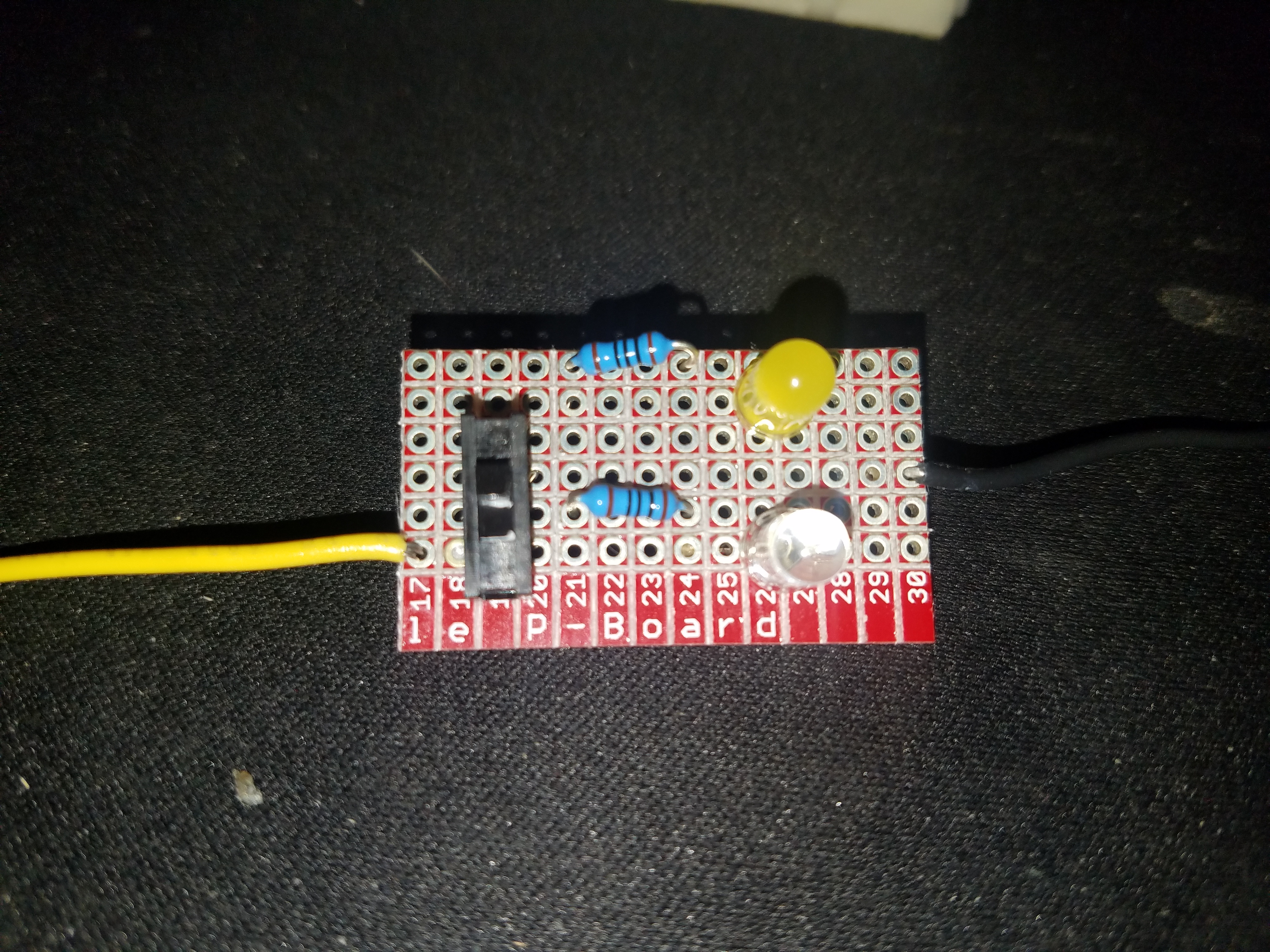
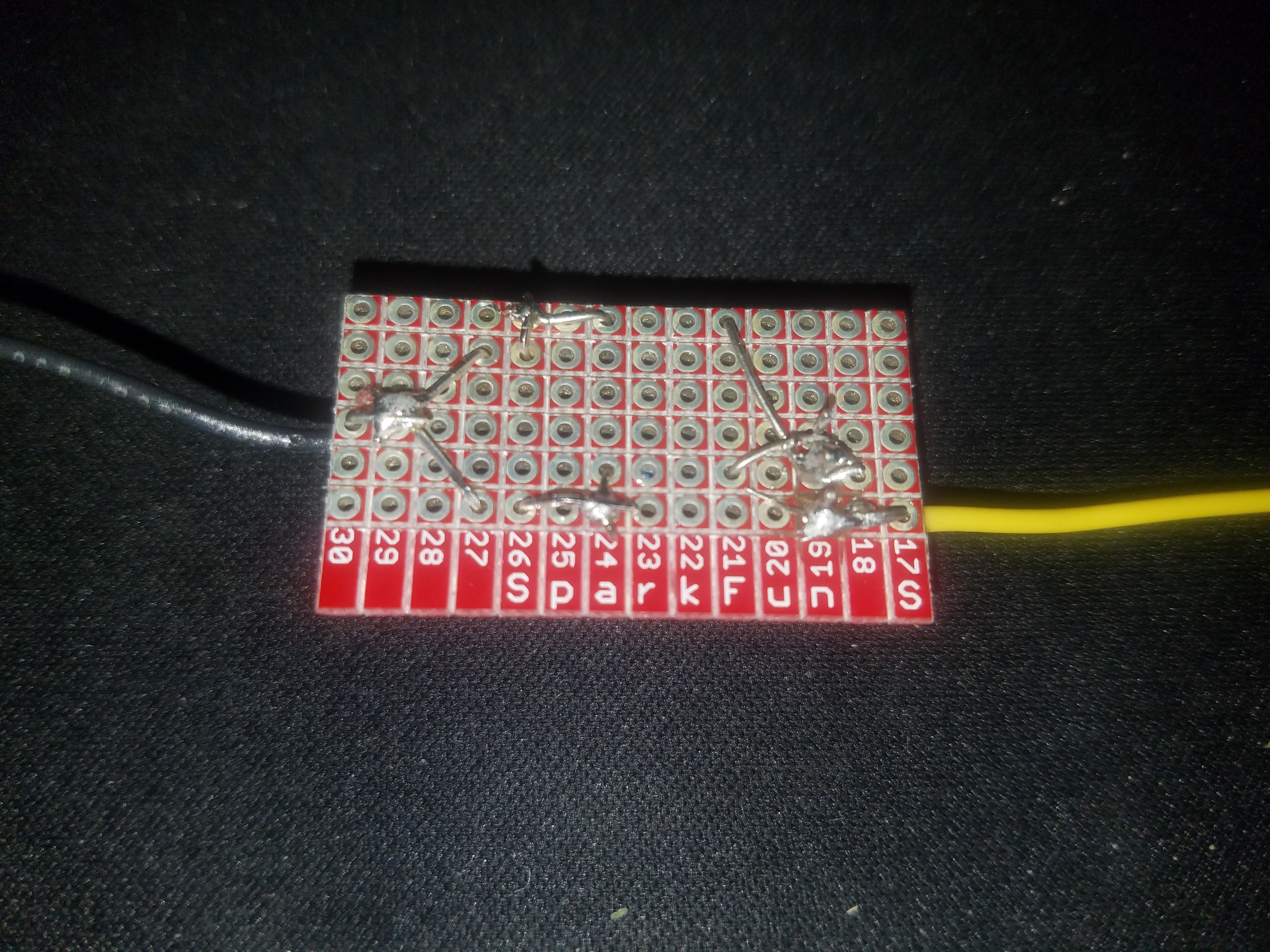
As you can see below, the soldering for the breakout board was more difficult than expected. The 100% tin solder also did not ease the process.
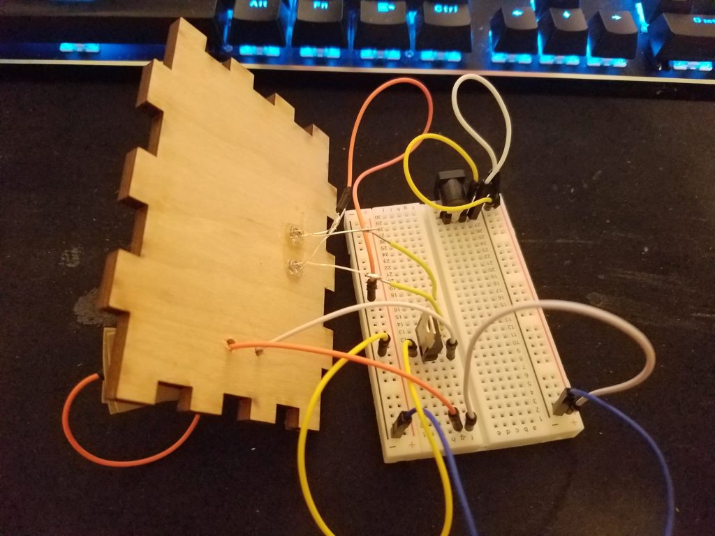
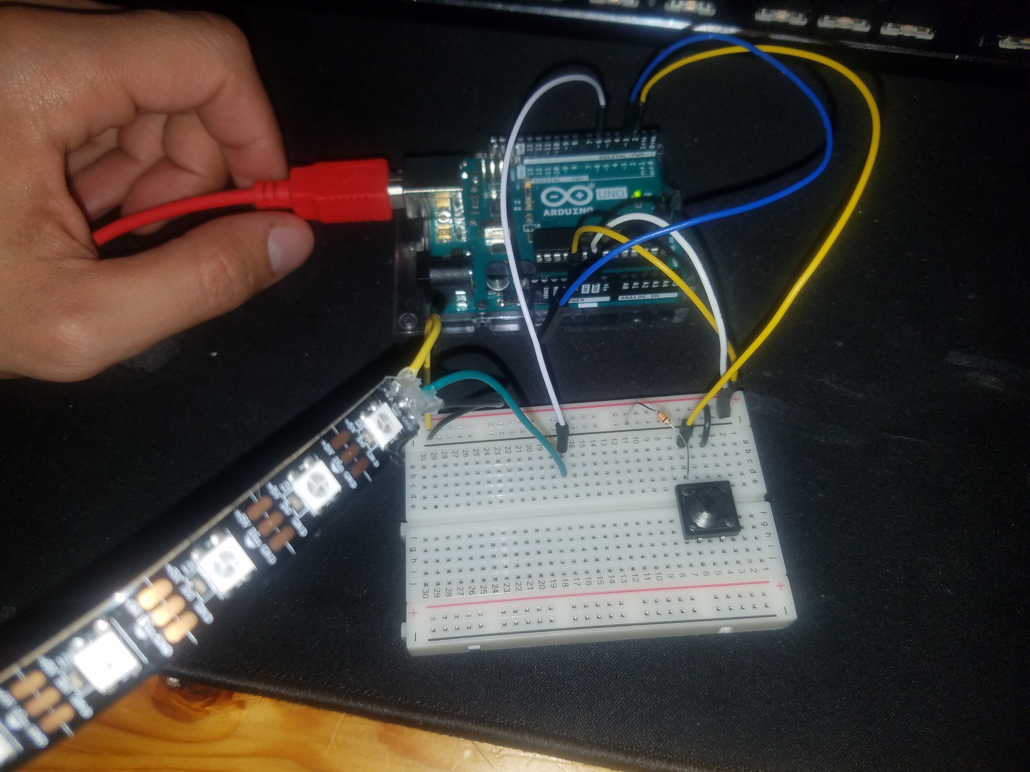
Part 2: Digital I/O
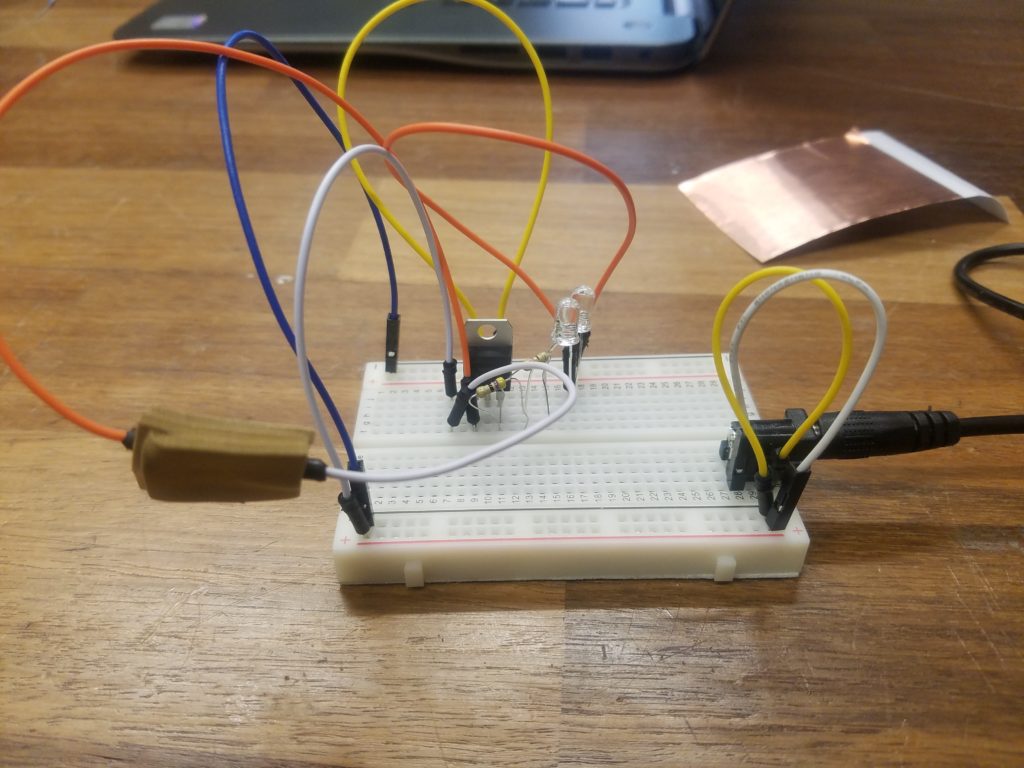
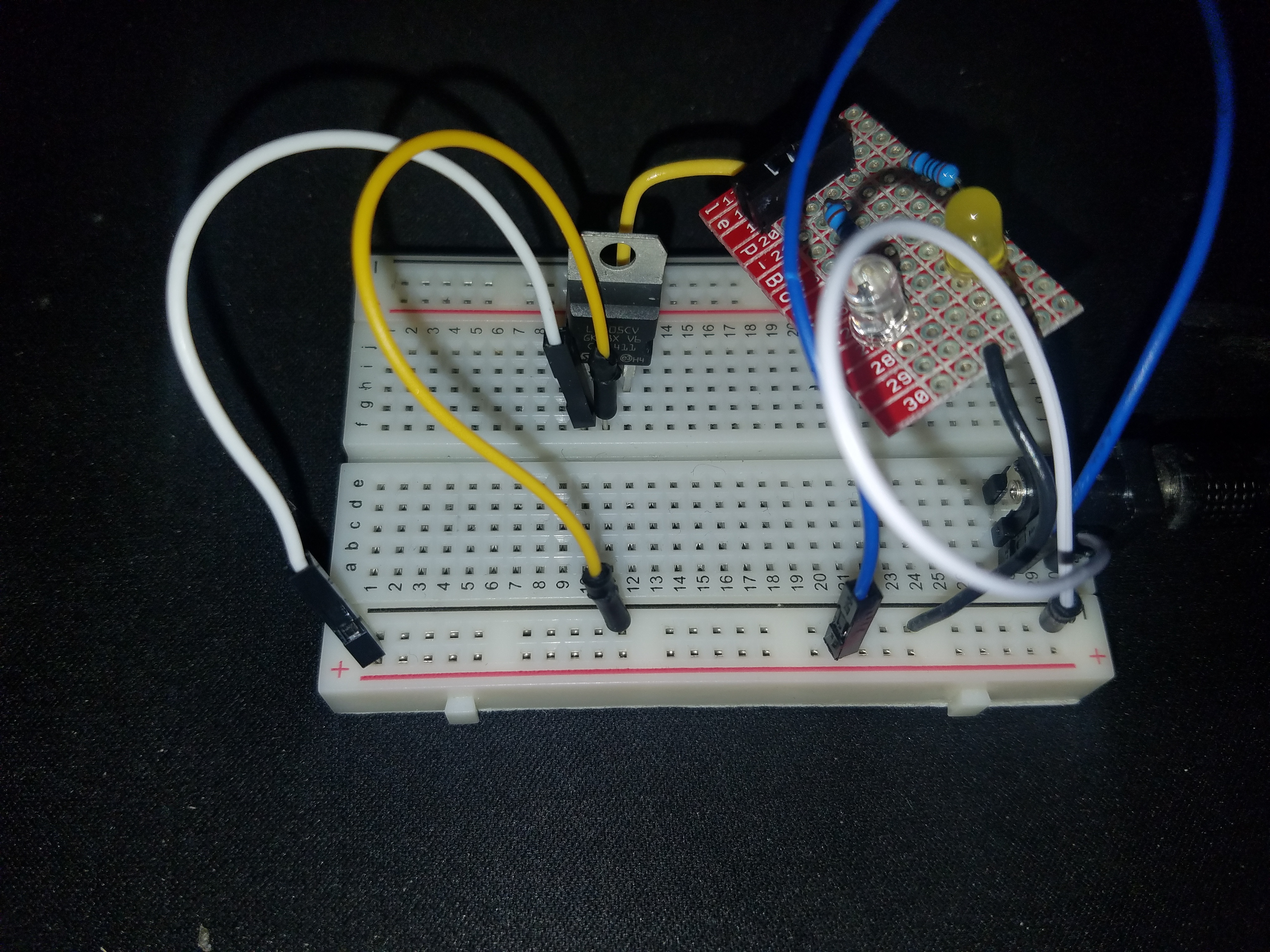
The next part incorporated the Arduino. For this we needed two inputs in the form of switches and an LED strip.
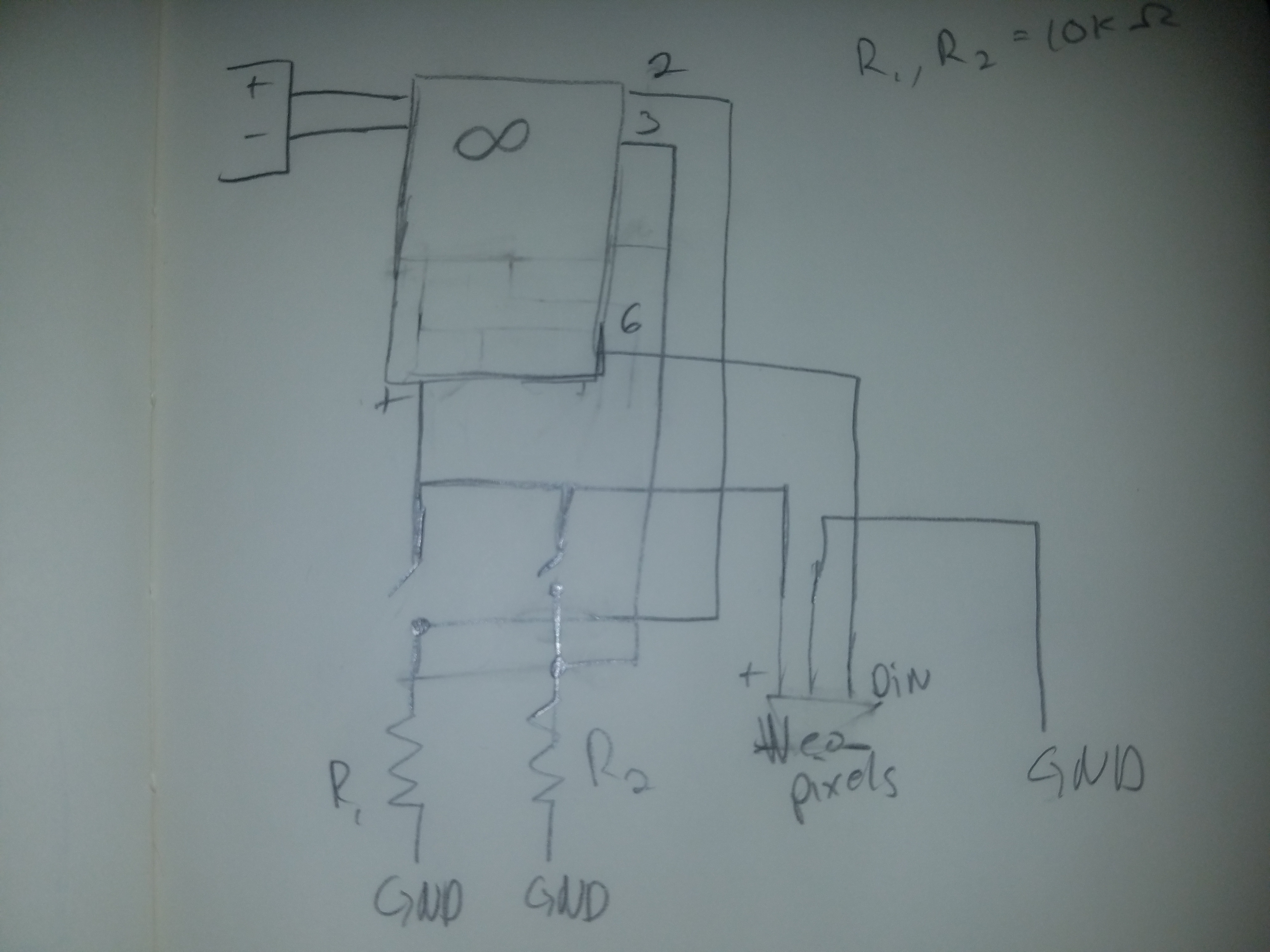
This schematic was particular annoying because, while I understood how it worked, I was not sure how to flatten it onto paper.
The schematic is conveniently simple with both switches and the LED strip being powered from the Arduino. Unfortunately, when I was making it I misplaced my resistors so the inputs would sometimes misfire.
For the logic I added four states made the LED light up in sequence with a correseponding color: white for both, red for one and green for the other. There was no output when neither switch was pressed.