Lab 1: Basic Electronics
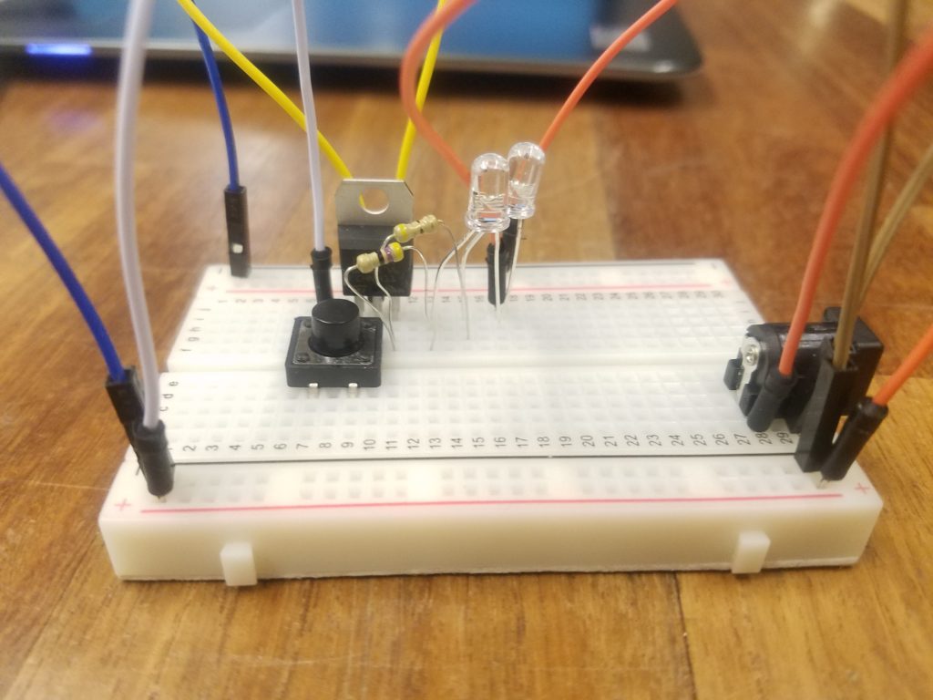
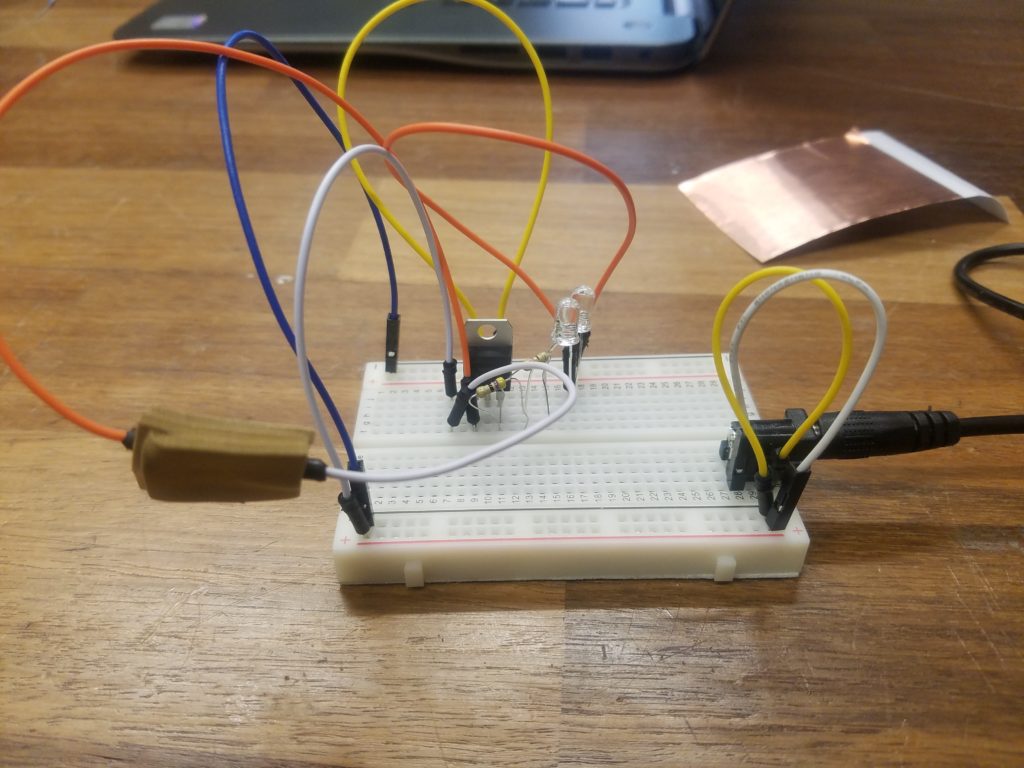
For this lab, we created a few basic electronic circuits from breadboards, jumper wires, LEDs, resistors, voltage regulators, and a power supply. The objective was to create two circuits: one of
LEDs in Series
For my LEDs in series, I choose blue LEDs which have a draw of 3.4V and .03A. Two of these in series would require more power than a voltage regulator woulod proveide at 5V so I wen without it.
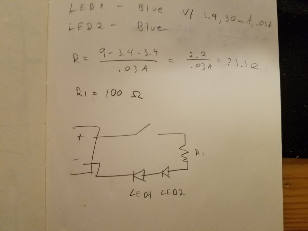
I used a 100Ω resistor which was slightly more than necessary but the piece worked charmingly.
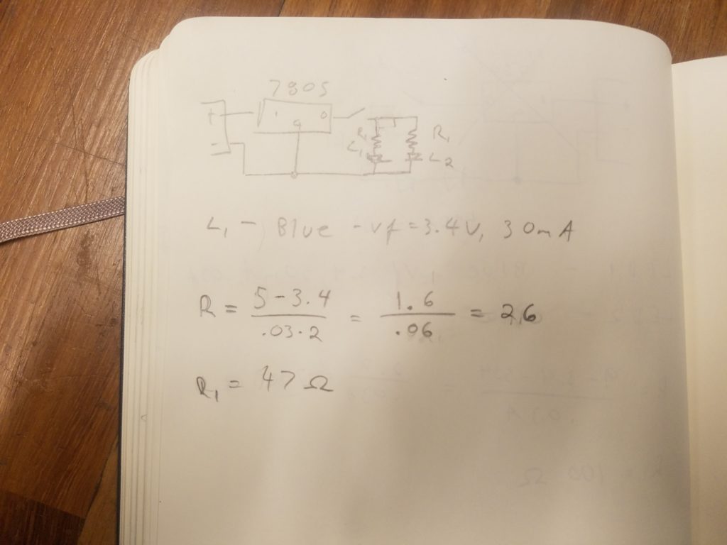
LEDs in Parallel
For the LEDs in parallel, I was able to use the voltage regulator with two 47Ω resistors which were slightly more than what was needed. Again, I used the blue LEDs.
Custom Switch
For the custom switch, I used three pieces of foam. The top and bottom had copper pieces attached to them with the wires on top of that. The middle one had a hole in the center so when the switch was pressed the two copper sheets touched and completed the circuit.
Originally, I had added the wires under the copper so the switch would have a definite off position but the glue on the copper tape prevented a current.
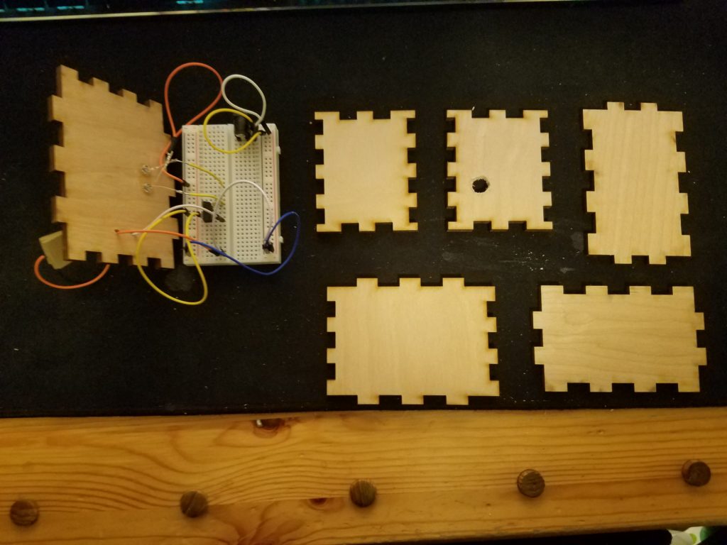
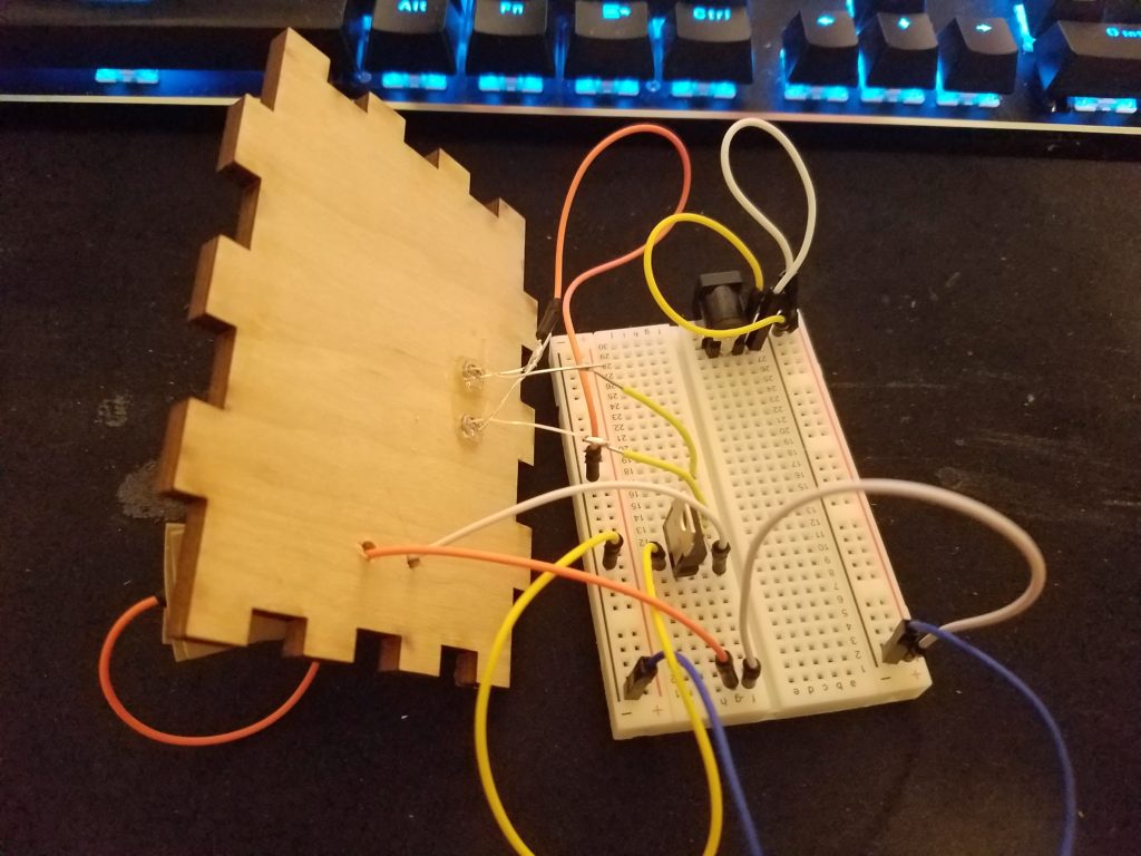
Creative Enclosure
For the creative enclosure, I laser cut a box and then added holes for the LEDs, switch wires, and power supply using a drill press. I then soldered the LEDs together to a wire. I also added wires to the power side of the LEDs so they could reach the board when it is fully assembled.