Object: Entry 3

Analog I/O

Part 1

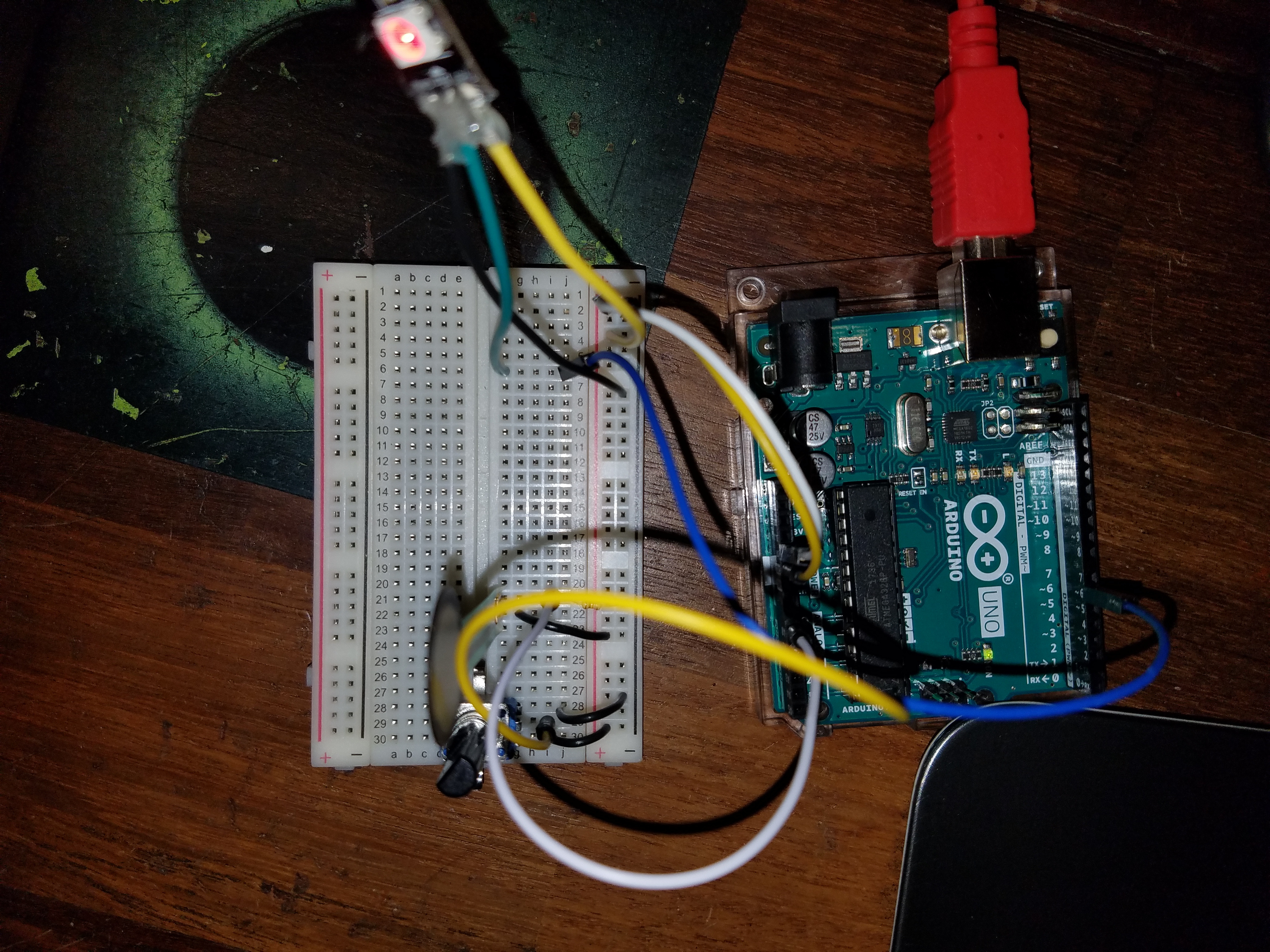
The first part of this lab was to create a simple analog input with varying output. For mine, I used a pressure sensor, a potentiometer, and NeoPixels to create a rudimentary strong man device. The number of lights corresponded to the pressure and the color was changed by rotating the potentiometer.

Schematics of part 1

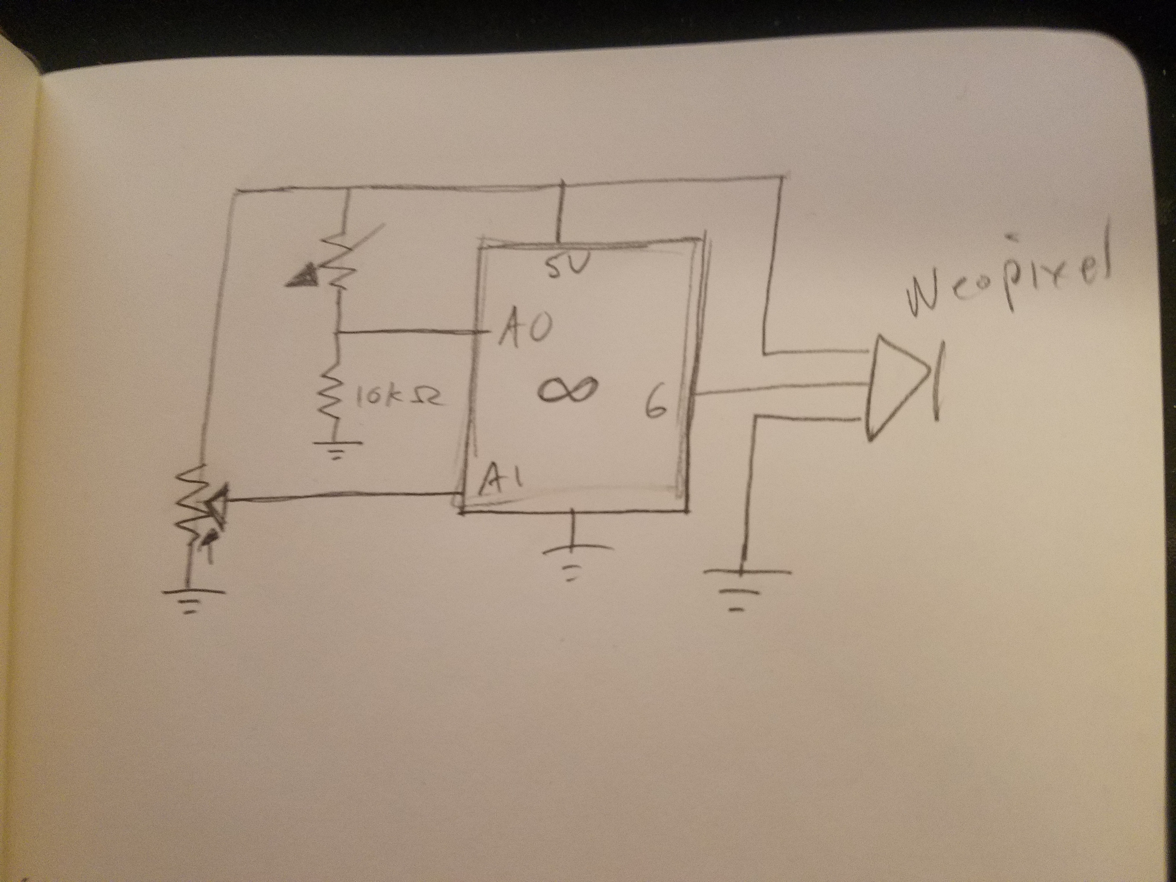
I adopted the WheelPosition function from the AdaFruit strandtest.ino in order to convert the scalar potentiometer readings to cyclic color values. The one issue with this code is that as it updates every half second some pixels were given colors and then not reassigned to blank after the pressure was removed causing the colors to appear off at times.

#include <Adafruit_NeoPixel.h>
#define PIN 6
Adafruit_NeoPixel strip = Adafruit_NeoPixel(5, PIN, NEO_GRB + NEO_KHZ800);
int pressure = A0;
int pot = A1;
int pressVal;
int potVal;
void setup() {
// put your setup code here, to run once:
Serial.begin(9600);
strip.begin();
strip.setBrightness(50);
strip.show();
}
void loop() {
// put your main code here, to run repeatedly:
pressVal = analogRead(pressure);
potVal = analogRead(pot);
int numLights = map(pressVal, 0, 1023, 0, 4);
uint32_t color = Wheel(map(potVal, 0, 1023, 0, 255));
// Set pixels up to pressure
for (int i = 0; i <= numLights; i++) {
strip.setPixelColor(i, color);
Serial.print(i);
Serial.print(" ");
}
Serial.println("pixels on");
strip.show();
delay(500);
// turn off all other lights
for (int i = numLights; i < strip.numPixels(); i++) {
strip.setPixelColor(i, 0);
Serial.print(i);
Serial.print(" ");
}
Serial.println("pixels off");
strip.show();
Serial.print(pressVal);
Serial.print(", ");
Serial.println(potVal);
delay(500);
}
// from strand test
// Input a value 0 to 255 to get a color value.
// The colours are a transition r - g - b - back to r.
uint32_t Wheel(byte WheelPos) {
WheelPos = 255 - WheelPos;
if(WheelPos < 85) {
return strip.Color(255 - WheelPos * 3, 0, WheelPos * 3);
}
if(WheelPos < 170) {
WheelPos -= 85;
return strip.Color(0, WheelPos * 3, 255 - WheelPos * 3);
}
WheelPos -= 170;
return strip.Color(WheelPos * 3, 255 - WheelPos * 3, 0);
}
Part 1 finished
Potentiometer readings in serial monitor
Video demonstration

Part 2

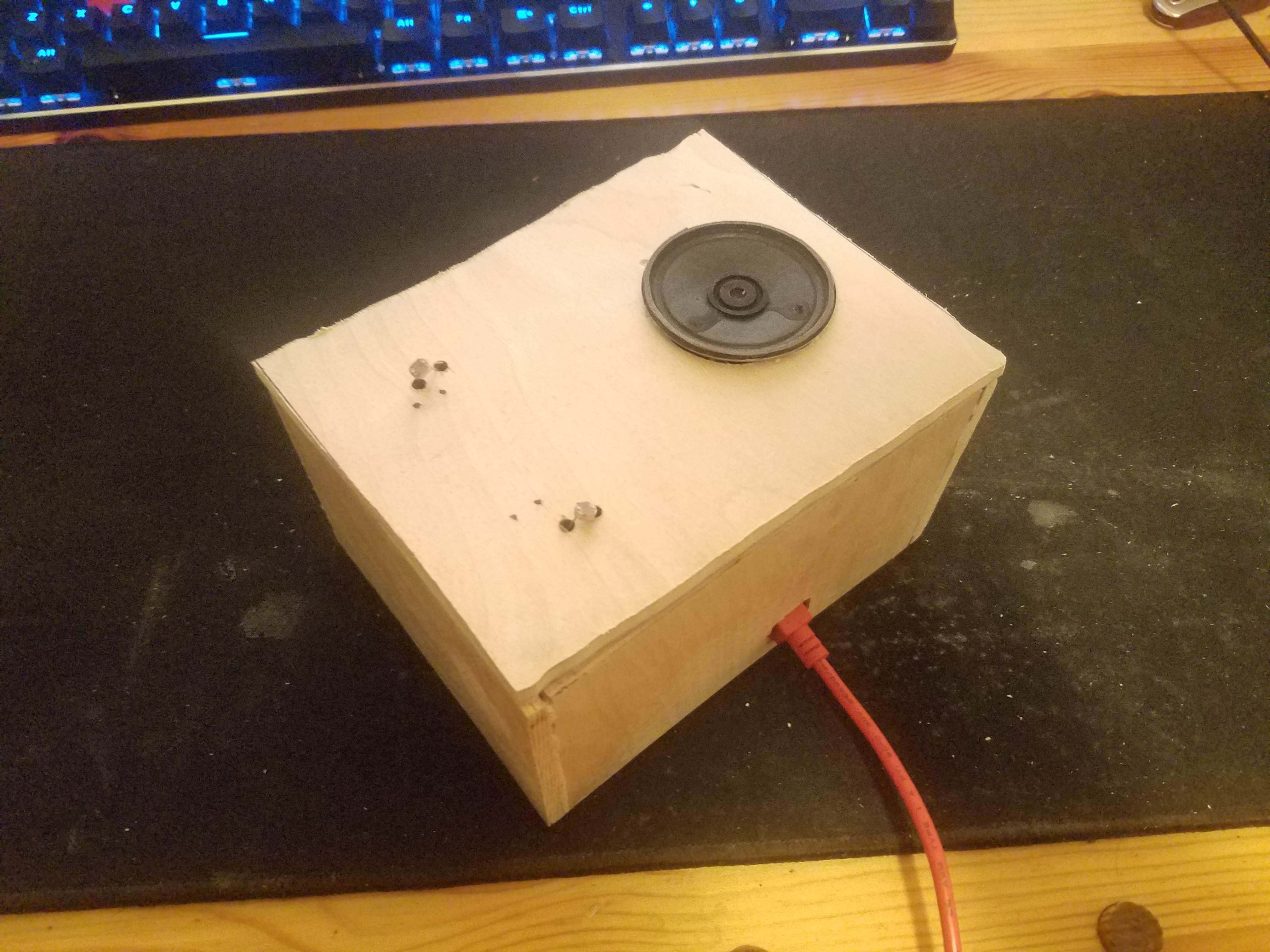
In the second part, we used an analog input to control the tone of a speaker. I found the random buzzing that was created to be annoying so I changed it to notes.

Schematics for part 2

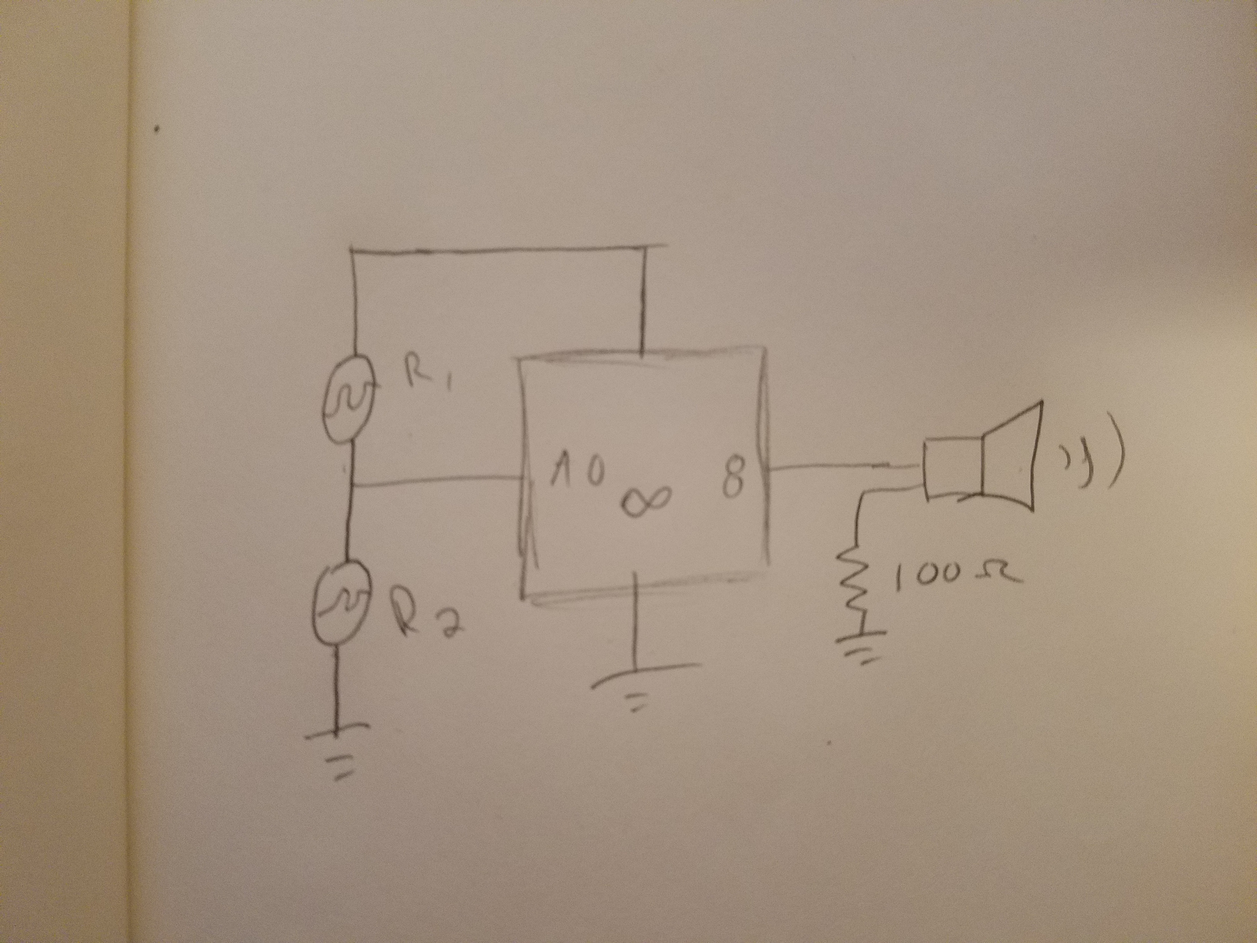
The note values were taken from Wikipedia.

int photo = A0;
int photoVal;
float freq_C = 261.63;
float freq_D = 293.66;
float freq_E = 329.63;
float freq_F = 349.23;
float freq_G = 392.00;
float freq_A = 440.0;
float freq_B = 493.88;
int noteDur = 500;
void setup() {
// put your setup code here, to run once:
Serial.begin(9600);
}
void loop() {
// put your main code here, to run repeatedly:
photoVal = map(analogRead(photo), 150, 500, 0, 6);
Serial.println(analogRead(photo));
switch (photoVal) {
case 0:
tone(8, freq_C);
break;
case 1:
tone(8, freq_D);
break;
case 2:
tone(8, freq_E);
break;
case 3:
tone(8, freq_F);
break;
case 4:
tone(8, freq_G);
break;
case 5:
tone(8, freq_A);
break;
case 6:
tone(8, freq_B);
break;
}
// tone(8, photoVal);
delay(10);
}
Part 2 testing

For this project, I made a box from plywood. Unfortunately, I was unable to locate my jigsaw and had to use a circular saw (which was too large for such a small project) and a dremel (which was too small). I made most of the pieces larger than needed and then sanded down to size.

Finished box
Video Demonstration