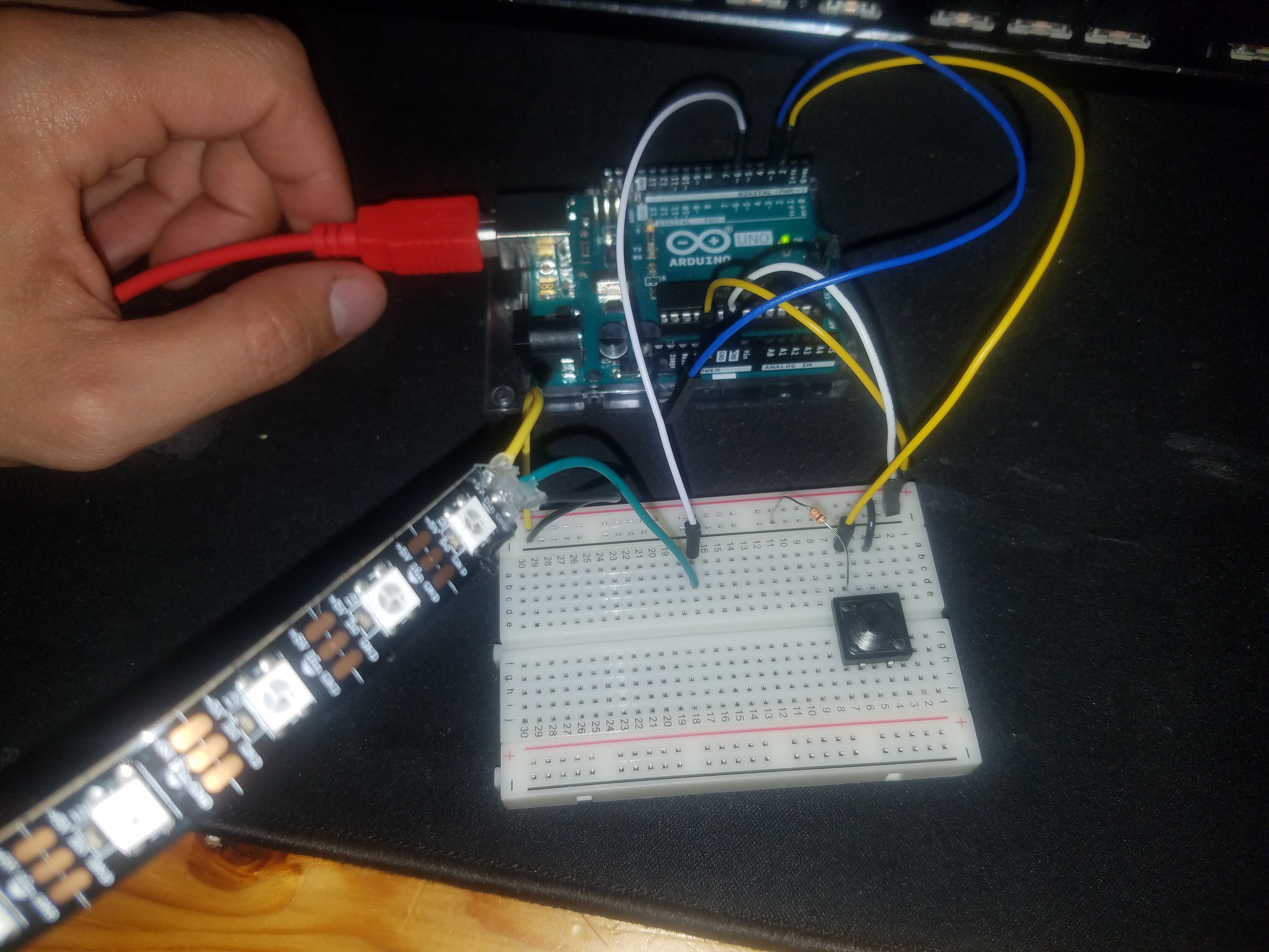
The first part of this lab was to create a simple analog input with varying output. For mine, I used a pressure sensor, a potentiometer, and NeoPixels to create a rudimentary strong man device. The number of lights corresponded to the pressure and the color was changed by rotating the potentiometer.
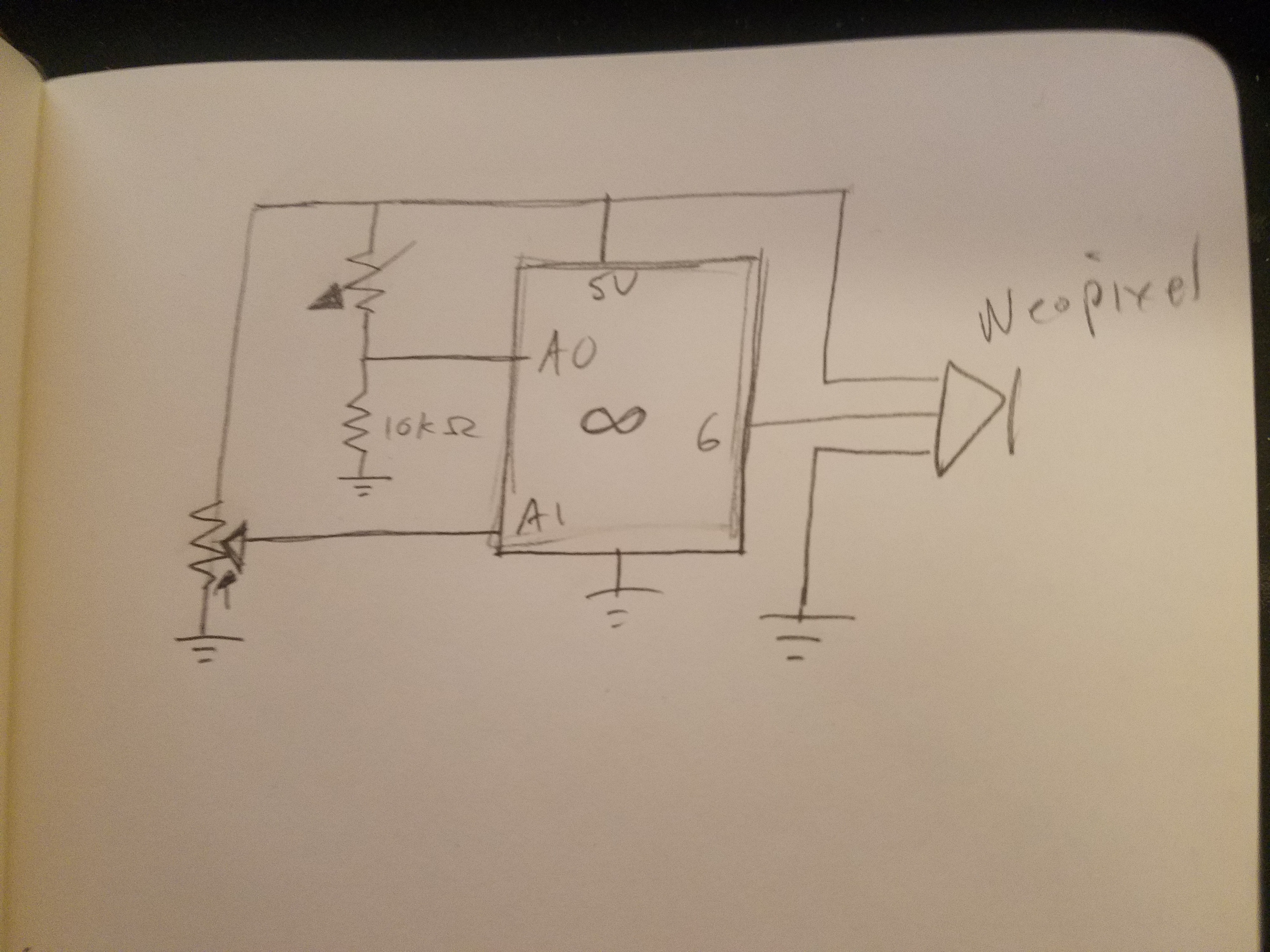
Schematics of part 1
I adopted the WheelPosition function from the AdaFruit strandtest.ino in order to convert the scalar potentiometer readings to cyclic color values. The one issue with this code is that as it updates every half second some pixels were given colors and then not reassigned to blank after the pressure was removed causing the colors to appear off at times.
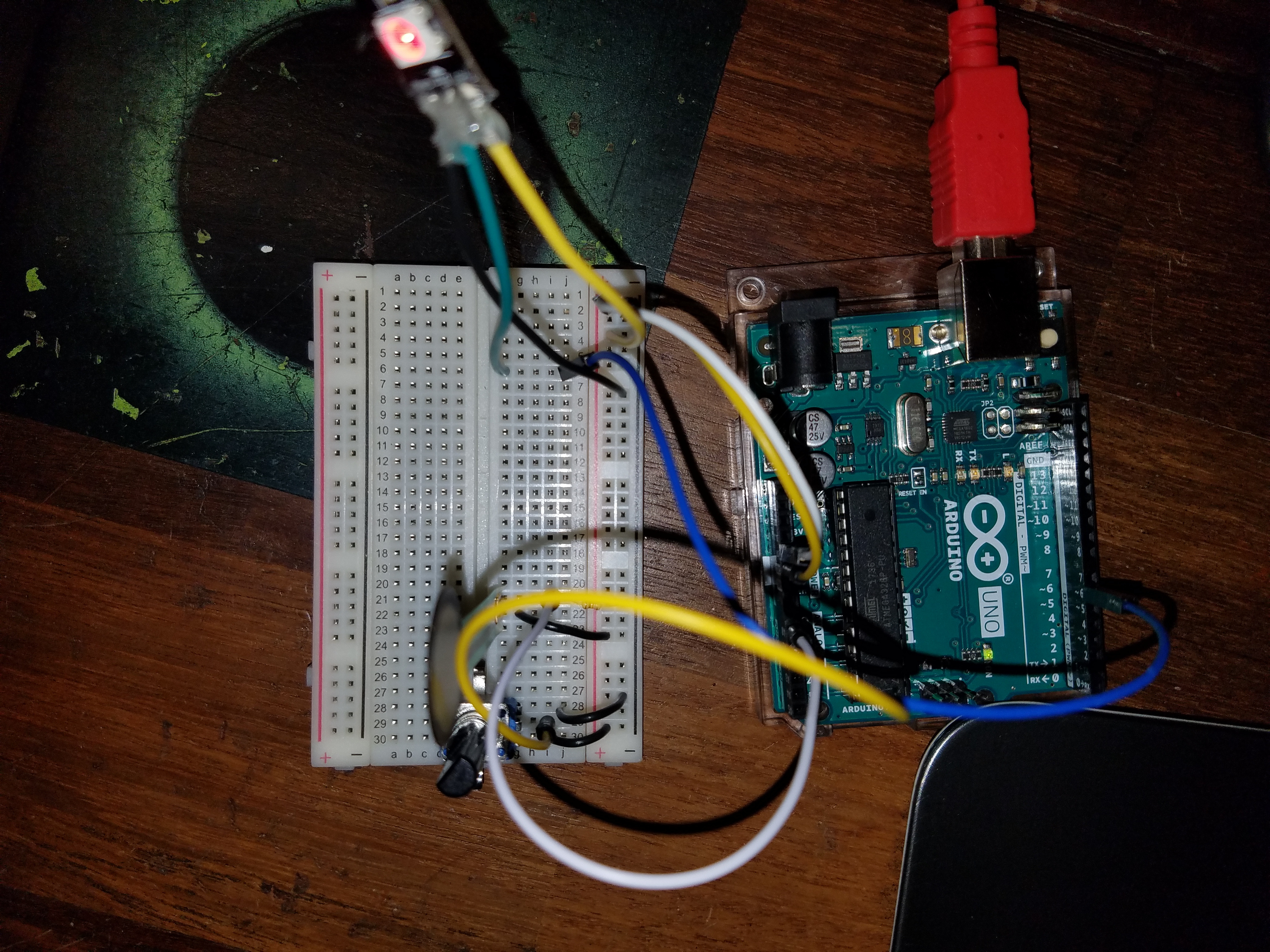
Part 1 finishedPotentiometer readings in serial monitorVideo demonstration
Part 2
In the second part, we used an analog input to control the tone of a speaker. I found the random buzzing that was created to be annoying so I changed it to notes.
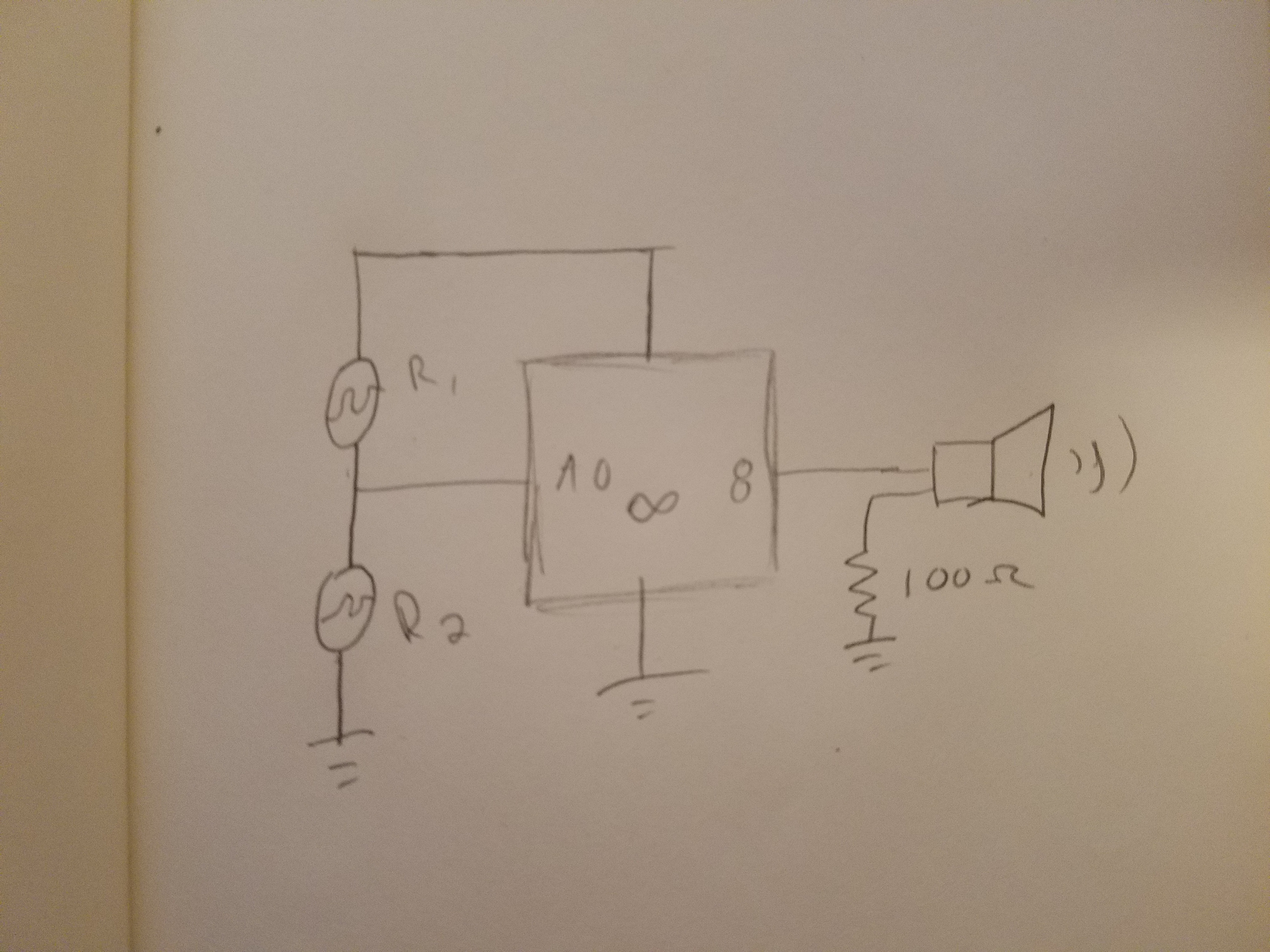
Schematics for part 2
The note values were taken from Wikipedia.
Part 2 testing
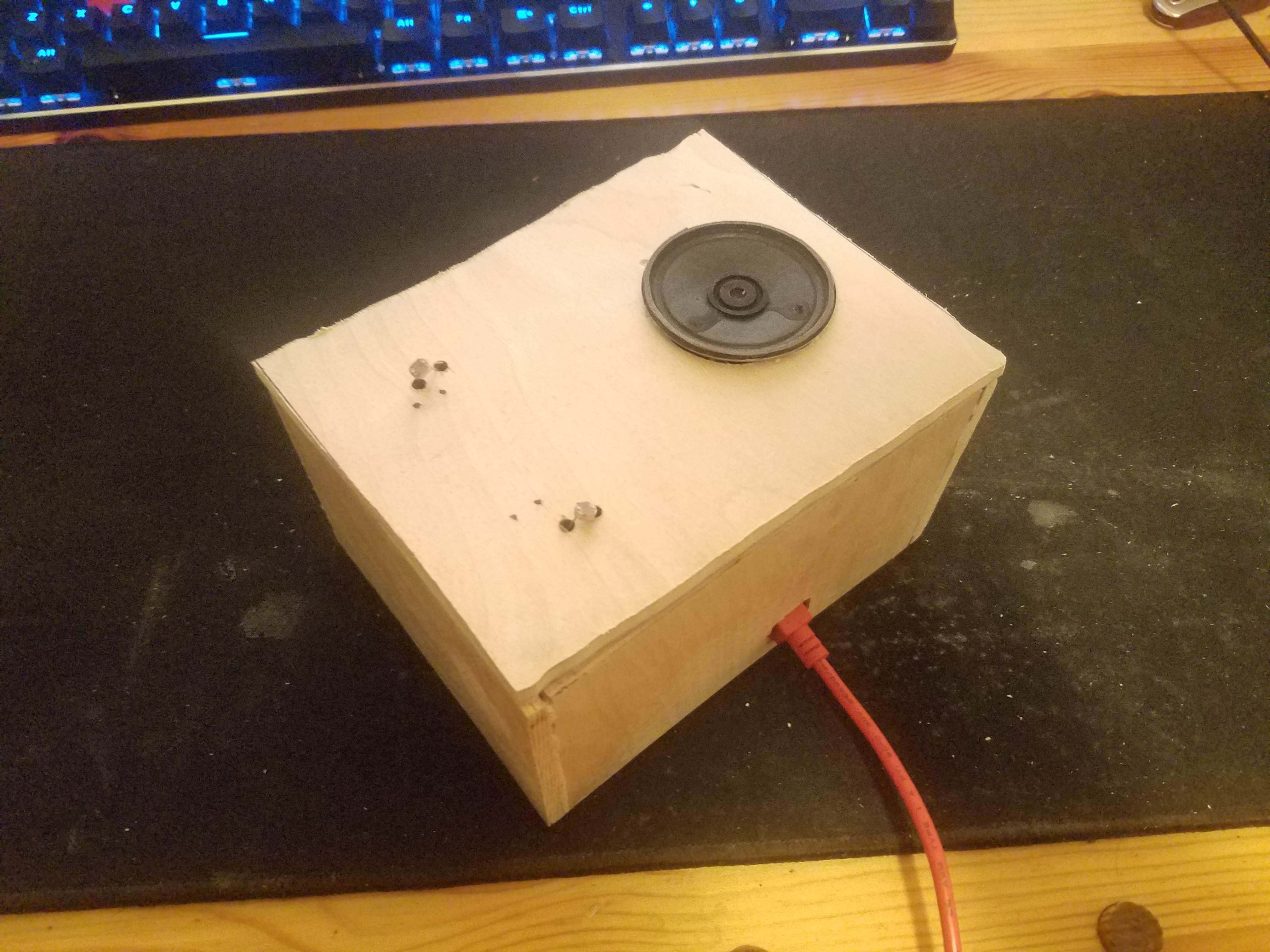
For this project, I made a box from plywood. Unfortunately, I was unable to locate my jigsaw and had to use a circular saw (which was too large for such a small project) and a dremel (which was too small). I made most of the pieces larger than needed and then sanded down to size.
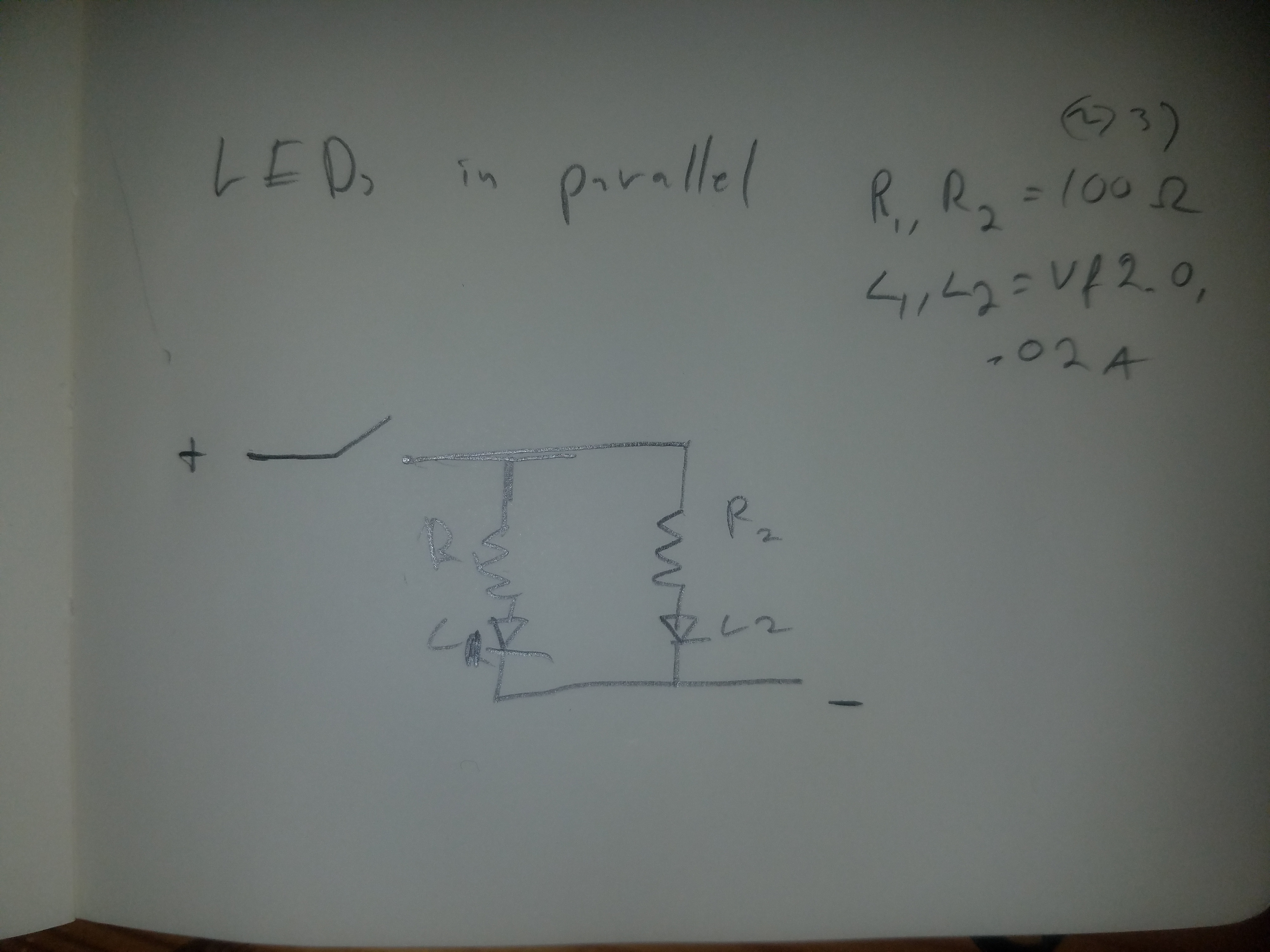
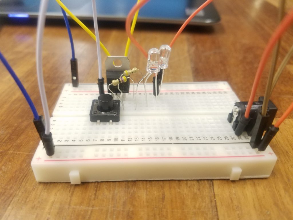
For this excercise, we created single parts of a circuits. For mine, I made 2 LEDs in parallel. This was harder as there were several wires that needed to be soldered together.
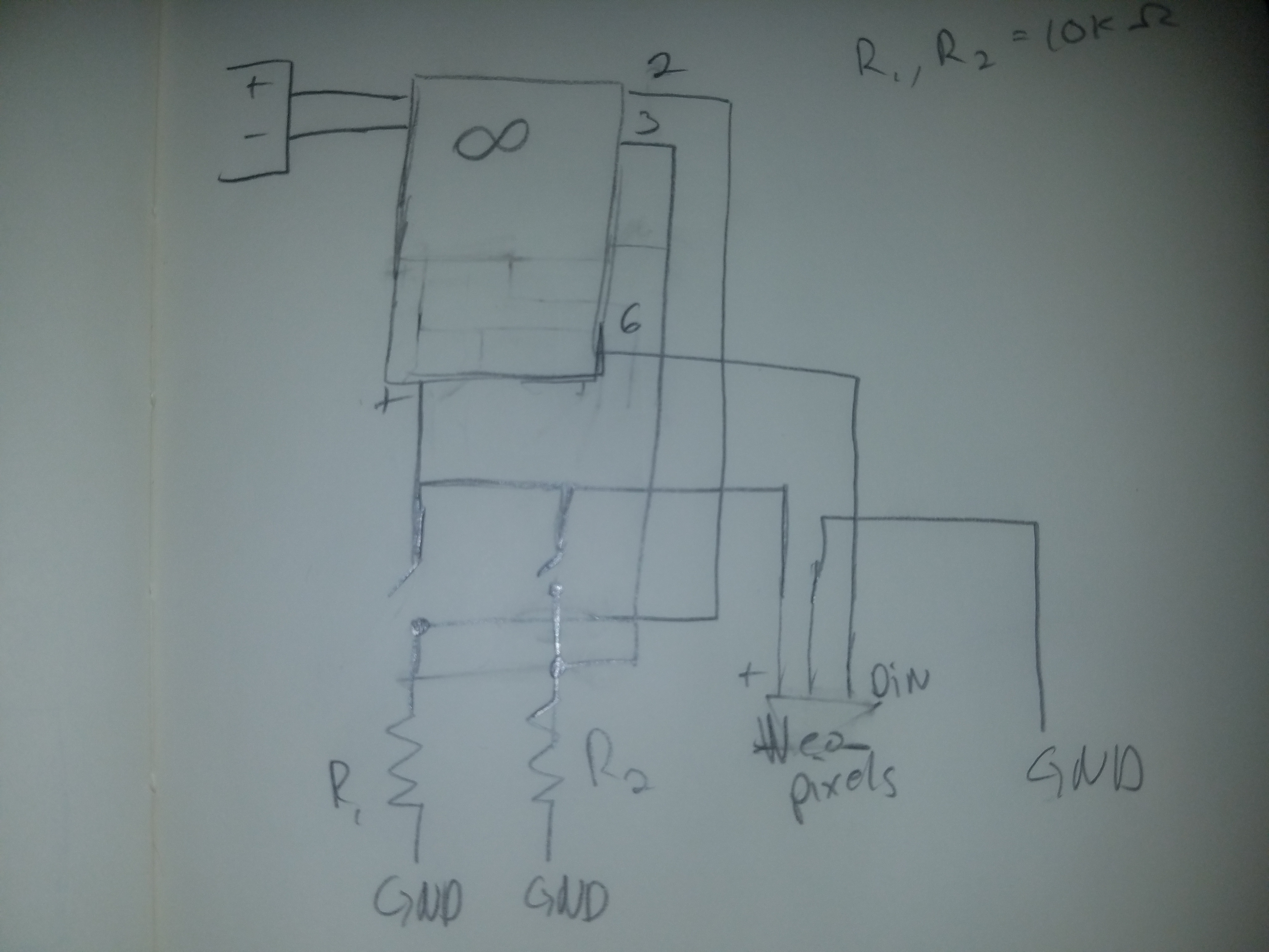
Schematic of LEDs in Parallel
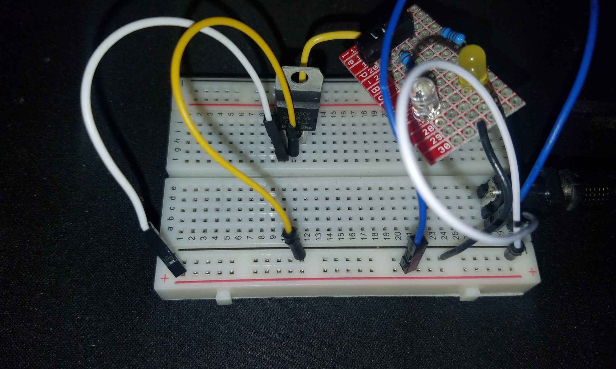
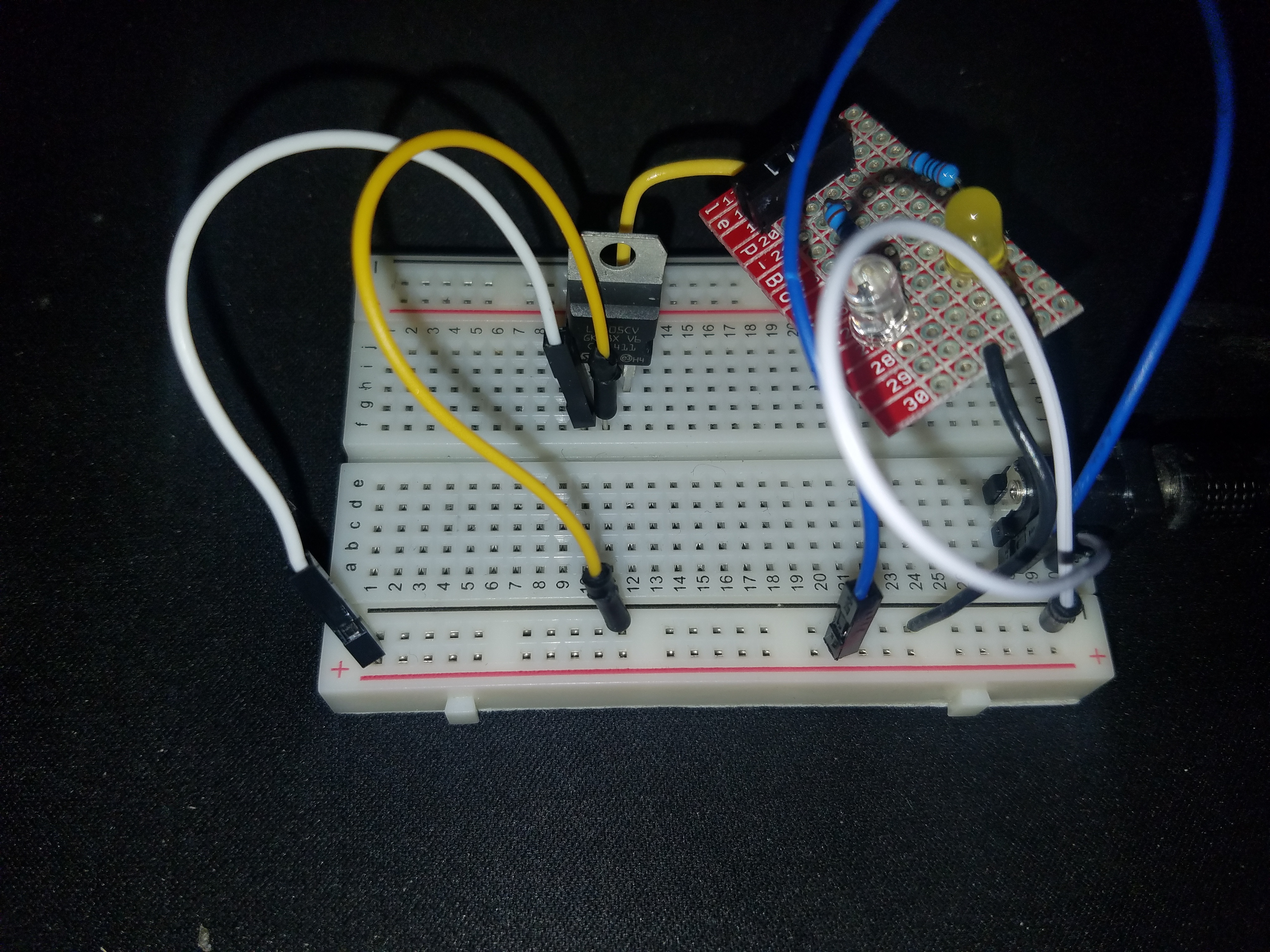
After calculating the resistance I set up the switch, resistors, and LEDs. Luckily both green and yellow LEDs have the same forward voltage so there was no need for extra calculations.
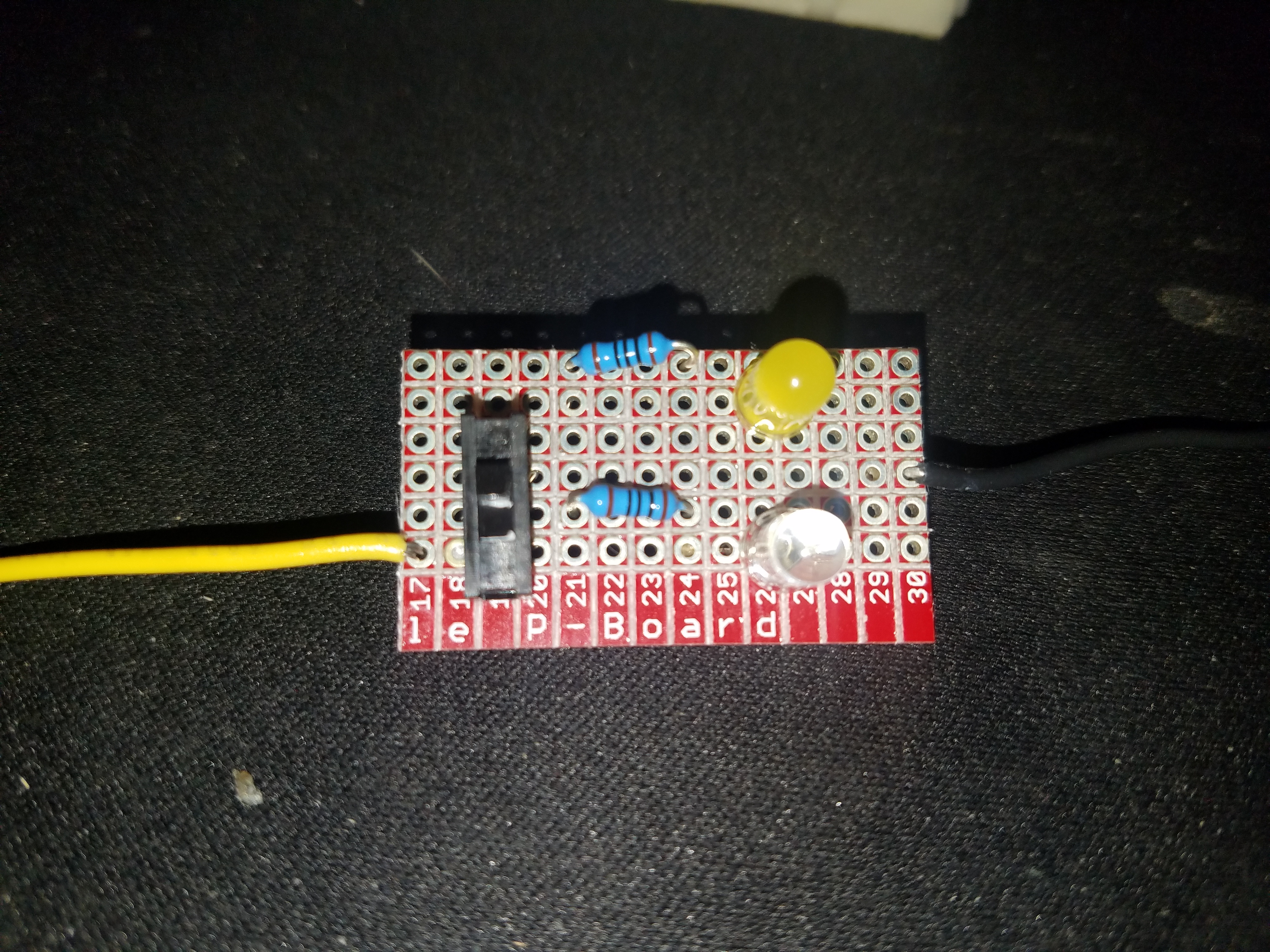
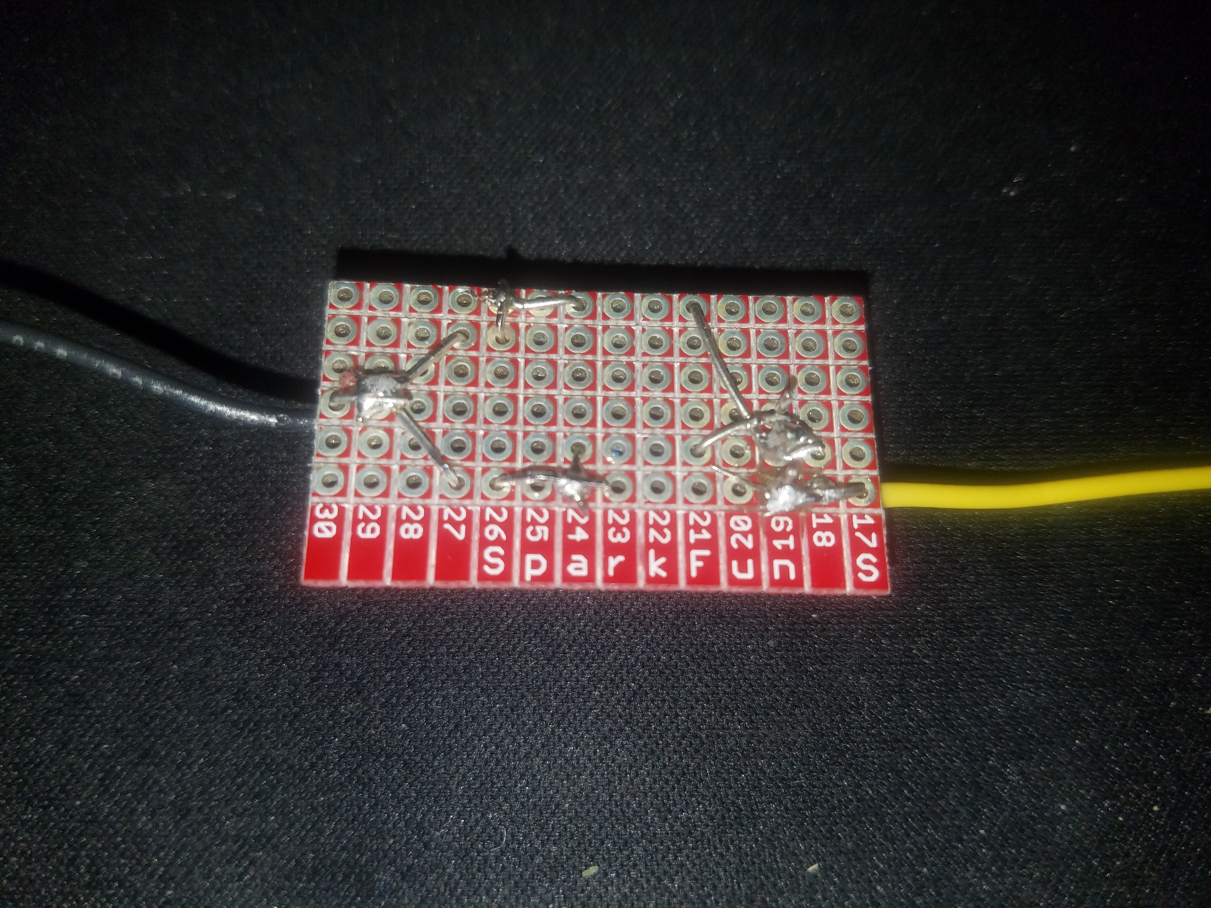
Finished breakout board
As you can see below, the soldering for the breakout board was more difficult than expected. The 100% tin solder also did not ease the process.
Back of breakout boardBreakout board attached to breadboardDemo of breakout board
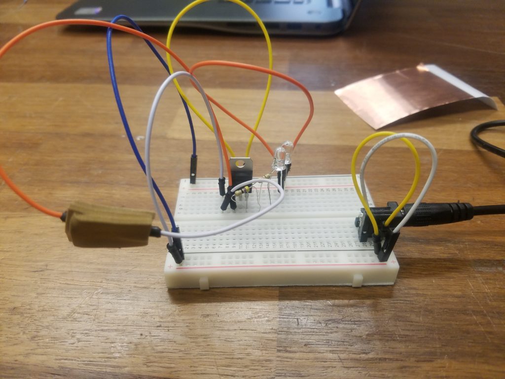
Part 2: Digital I/O
The next part incorporated the Arduino. For this we needed two inputs in the form of switches and an LED strip.
Schematic
This schematic was particular annoying because, while I understood how it worked, I was not sure how to flatten it onto paper.
The schematic is conveniently simple with both switches and the LED strip being powered from the Arduino. Unfortunately, when I was making it I misplaced my resistors so the inputs would sometimes misfire.
Finish product
For the logic I added four states made the LED light up in sequence with a correseponding color: white for both, red for one and green for the other. There was no output when neither switch was pressed.
For this lab, we created a few basic electronic circuits from breadboards, jumper wires, LEDs, resistors, voltage regulators, and a power supply. The objective was to create two circuits: one of LEDs in series and one of LEDs in parallel.
LEDs in Series
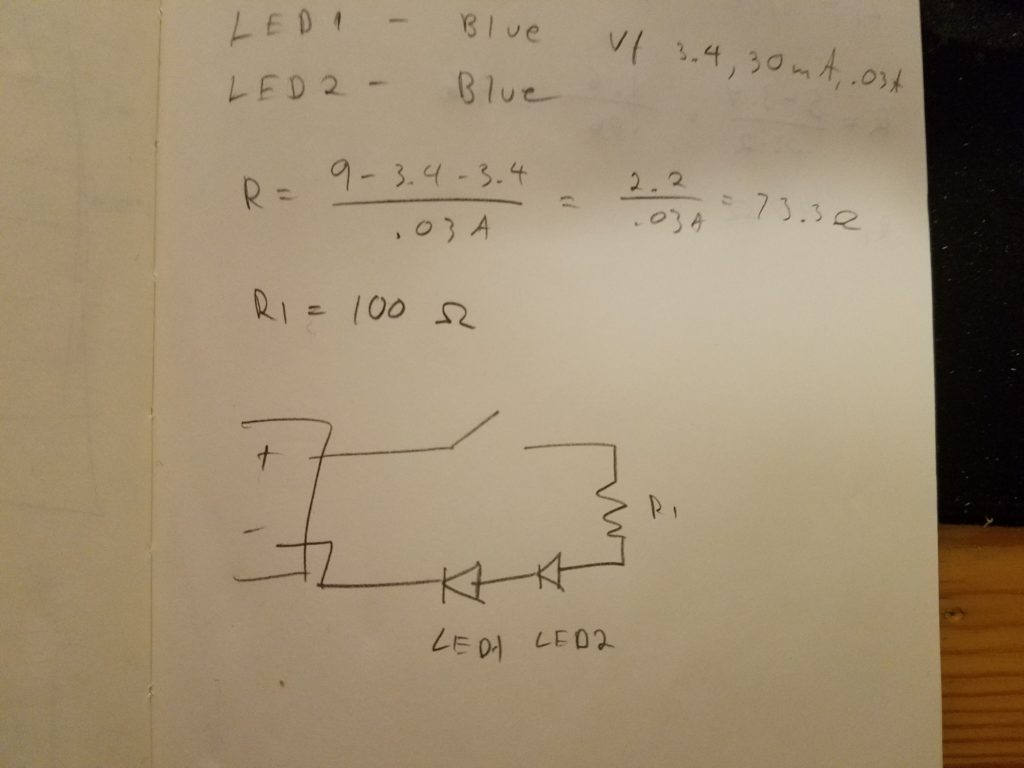
For my LEDs in series, I choose blue LEDs which have a draw of 3.4V and .03A. Two of these in series would require more power than a voltage regulator woulod proveide at 5V so I wen without it.
Schematic of LEDs in paralell with calculations of resistors
I used a 100Ω resistor which was slightly more than necessary but the piece worked charmingly.
LEDs in Parallel
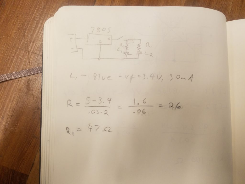
For the LEDs in parallel, I was able to use the voltage regulator with two 47Ω resistors which were slightly more than what was needed. Again, I used the blue LEDs.
Schematic with calculationsFinal circuitDemonstration of final product
Custom Switch
For the custom switch, I used three pieces of foam. The top and bottom had copper pieces attached to them with the wires on top of that. The middle one had a hole in the center so when the switch was pressed the two copper sheets touched and completed the circuit.
Originally, I had added the wires under the copper so the switch would have a definite off position but the glue on the copper tape prevented a current.
Final product.Demonstration of final product
Creative Enclosure
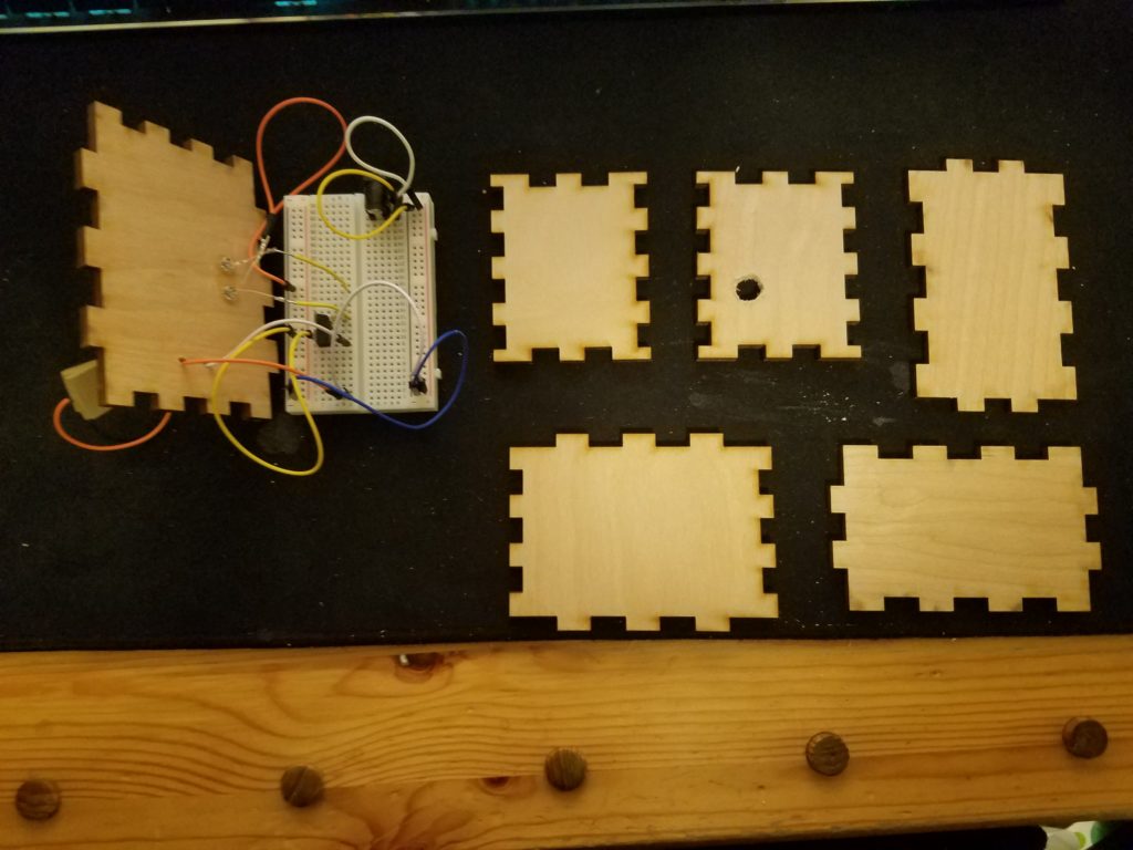
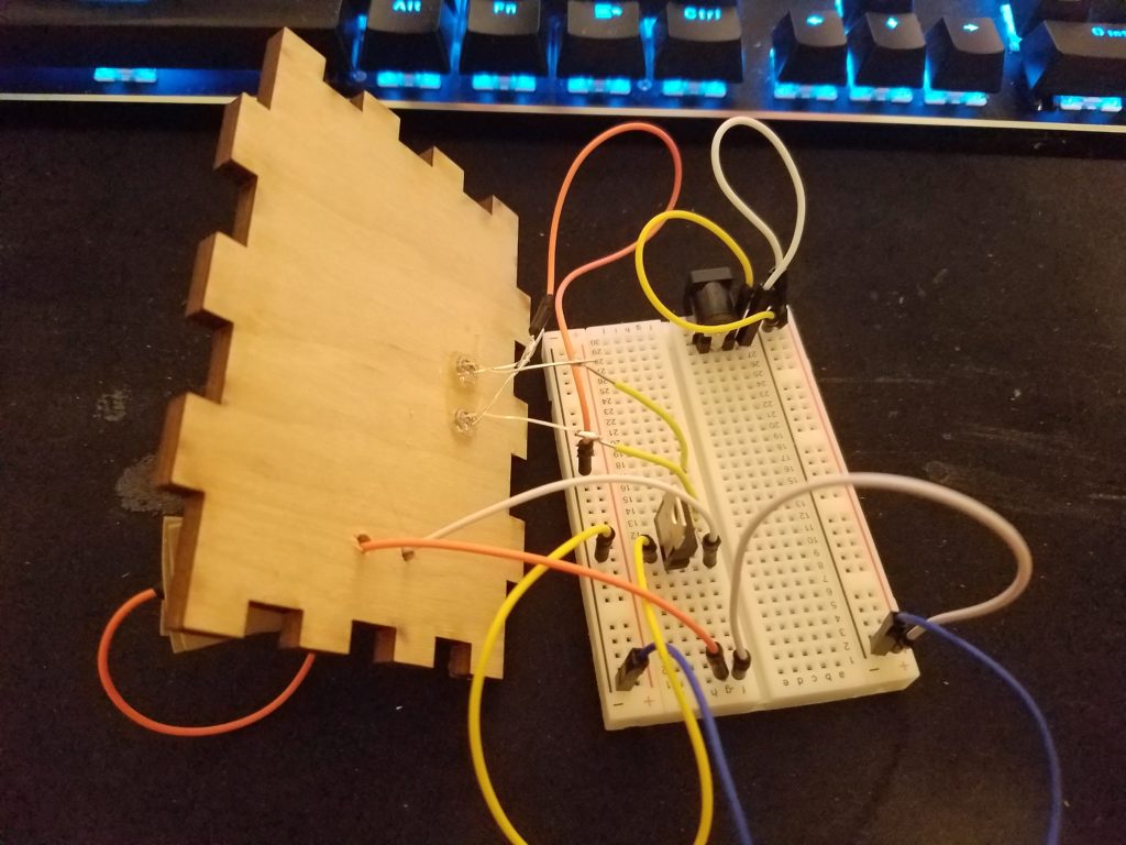
For the creative enclosure, I laser cut a box and then added holes for the LEDs, switch wires, and power supply using a drill press. I then soldered the LEDs together to a wire. I also added wires to the power side of the LEDs so they could reach the board when it is fully assembled.
Pieces of the board after gluing the LEDs to the topClose up of bread board and top of boxDemonstration of finished product